Angular Contact Ball Bearings Explained: Contact Angle, Load Capacity, and Common Uses
Author
Date Published
Reading Time
Why do angular contact ball bearings matter in industrial systems?
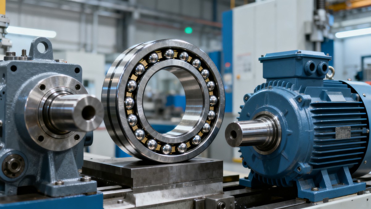
Angular contact ball bearings sit behind many machines that cannot tolerate unstable motion, heat buildup, or premature failure.
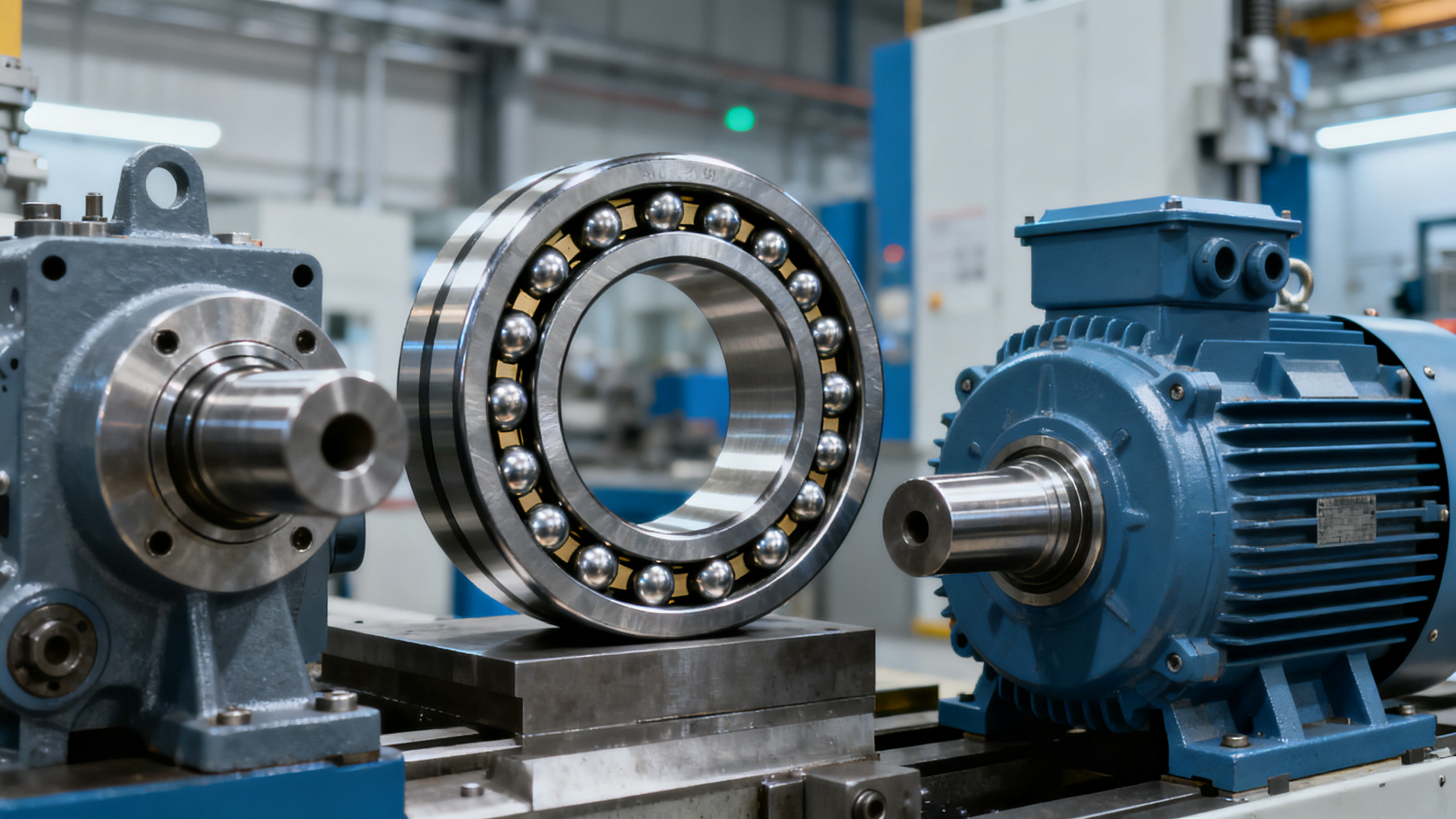
They are designed to support radial load and axial load at the same time.
That single feature explains why they appear in pumps, compressors, gearboxes, machine tools, electric motors, and precision drive assemblies.
In simple terms, the raceways are offset.
This creates a contact angle between the balls and raceways, allowing the bearing to carry thrust load more effectively than a standard deep groove ball bearing.
That matters in industrial environments where rotation speed is high, shaft alignment must stay controlled, and unplanned downtime becomes expensive very quickly.
Within GIC’s mechanical and metallurgy coverage, angular contact ball bearings are often discussed as a component-level decision with system-level consequences.
A bearing that is slightly mismatched to load direction or preload can reduce efficiency, shorten lubrication life, and create vibration that affects adjacent equipment.
So the basic question is not only what angular contact ball bearings are.
It is whether the contact angle, arrangement, cage design, and quality level fit the operating reality.
What exactly does the contact angle change?
This is where most selection mistakes begin.
The contact angle determines how the bearing balances speed capability against axial load capacity.
A smaller angle, such as 15 degrees, generally supports higher speed and lower axial load.
A larger angle, such as 40 degrees, usually handles greater thrust load but at lower speed potential.
In actual applications, the choice is rarely made by angle alone.
Engineers also look at shaft stiffness, thermal growth, lubrication method, and whether the load is steady or reversing.
The quick comparison below helps frame that decision.
More commonly, the right angle is the one that matches actual loading direction over the full duty cycle, not just peak load on paper.
That is especially important where CE, ISO, or plant reliability targets require evidence that a component choice is technically justified.
Where do angular contact ball bearings perform best?
They perform best where radial load is combined with meaningful axial force, and where running accuracy matters.
This usually means rotating equipment with one or more of the following conditions.
- High shaft speed with moderate thrust
- Bidirectional axial load when used in matched pairs
- Tight positioning accuracy requirements
- Low vibration expectations in precision assemblies
- Compact designs where larger roller bearings are impractical
For example, centrifugal pumps often generate axial thrust due to impeller action.
A properly selected angular contact ball bearing can stabilize the shaft while preserving speed capability.
Machine tool spindles are another familiar case.
There, angular contact ball bearings help maintain stiffness, rotational precision, and surface finish quality.
Electric motors and servo systems also use them when axial positioning and smooth rotation affect control accuracy.
The weaker fit is a slow, shock-heavy application with severe contamination and very high radial load.
In that situation, a cylindrical roller or tapered roller bearing may be the more durable choice.
Single, duplex, or matched sets: which configuration makes sense?
This question comes up after the basic bearing type is confirmed.
Single-row angular contact ball bearings usually support axial load in one direction.
If the application sees thrust from both directions, pairing becomes necessary.
Common paired arrangements include back-to-back, face-to-face, and tandem.
Each changes stiffness, moment capacity, and the way the assembly responds to misalignment.
A quick rule of thumb helps.
- Back-to-back pairs improve rigidity and resist overturning moments well.
- Face-to-face pairs tolerate slight misalignment more easily.
- Tandem pairs increase axial capacity in one direction.
Matched sets matter because preload and internal geometry are controlled at the factory.
Without that control, the pair may run hotter, lose stiffness, or carry load unevenly.
In regulated industrial projects, that uneven loading can complicate maintenance planning and root-cause analysis later.
That is why technical sourcing reviews often treat the bearing arrangement as seriously as the bearing size itself.
How should selection decisions be made beyond catalog ratings?
Catalog numbers are only the starting point.
For angular contact ball bearings, operating reliability depends on surrounding conditions that are easy to underestimate.
A practical evaluation usually includes the checklist below.
In practice, this is where broad industrial intelligence becomes useful.
GIC’s approach to foundational engineering emphasizes verified technical context, not only dimensional interchangeability.
That means looking at standards, operating risk, and lifecycle impact together.
What are the most common mistakes with angular contact ball bearings?
The first mistake is assuming all angular contact ball bearings behave similarly if the size matches.
They do not.
Contact angle, preload class, cage material, and precision grade can change performance significantly.
Another common issue is treating axial load as occasional when it is actually continuous.
That usually leads to an underspecified arrangement.
Installation errors are also frequent.
Too much mounting force, poor cleanliness, or incorrect preload setting can damage the bearing before startup.
A fourth mistake involves lubrication assumptions.
High-speed angular contact ball bearings may need a very different grease or oil strategy than slower bearings nearby.
Finally, some teams evaluate price per unit without considering inspection records, traceability, and consistency between production batches.
For critical infrastructure or heavy process equipment, those details are not administrative extras.
They are part of risk control.
So how do you narrow down the right bearing with confidence?
A useful way to decide is to work from operating conditions outward.
Start with actual radial and axial loads, including transient events.
Then confirm speed, duty cycle, temperature, and lubrication limits.
After that, review whether one bearing or a matched set is needed.
The final filter should include mounting accuracy, contamination control, and compliance expectations.
Angular contact ball bearings are often the right answer when precision, combined loads, and speed must coexist.
But they deliver that value only when the contact angle and arrangement are chosen deliberately.
If the next step is a real selection exercise, gather shaft data, load direction, thermal conditions, and target service life first.
That creates a clearer basis for comparing options, checking standards, and reducing avoidable lifecycle cost.
Technical Specifications
- How to Select Electronic Hotel Key Card Locks for Guest Rooms and Staff AreasAuthor :Safety Compliance Lead
- How to Select Lab Instruments for Reliable Chemical Analysis WorkflowsAuthor :Precision Metrology Expert
- How to Size a UPS for Server Rooms: Load, Runtime, and Redundancy FactorsAuthor :Grid Infrastructure Analyst
Expert Insights

Chief Security Architect
Dr. Thorne specializes in the intersection of structural engineering and digital resilience. He has advised three G7 governments on industrial infrastructure security.
Related Analysis
- Sep 17, 2026How to Select Electronic Hotel Key Card Locks for Guest Rooms and Staff AreasAuthor :Safety Compliance Lead
- Sep 16, 2026How to Select Lab Instruments for Reliable Chemical Analysis WorkflowsAuthor :Precision Metrology Expert
- Sep 15, 2026How to Size a UPS for Server Rooms: Load, Runtime, and Redundancy FactorsAuthor :Grid Infrastructure Analyst
Core Sector // 01
Security & Safety
- Selecting Low-Friction Pneumatic Seals for High-Cycle, Low-Pressure CylindersAuthor :Heavy Industry Strategist

- Selecting Spherical Roller Bearings for Mining: Load, Contamination, and Service LifeAuthor :Heavy Industry Strategist

- Do Deep Groove Ball Bearings Need Special Seals in Coastal Humidity?Author :Heavy Industry Strategist

- How to Select Anti Vibration Rubber Shock Absorbers for Machinery and EquipmentAuthor :Heavy Industry Strategist

- When to Specify Induction Hardened Slewing Ring Bearings for Heavy-Duty EquipmentAuthor :Heavy Industry Strategist

- How to Evaluate Weather Resistant EPDM Extrusion for Outdoor Sealing ApplicationsAuthor :Heavy Industry Strategist

- Bearing and Seal Lead Times Stretch to 22 WeeksAuthor :Heavy Industry Strategist

- Angular Contact Ball Bearings Explained: Contact Angle, Load Capacity, and Common UsesAuthor :Heavy Industry Strategist