Selecting High-Temperature Gaskets for Steam, Flanges, and Thermal Cycling
Author
Date Published
Reading Time
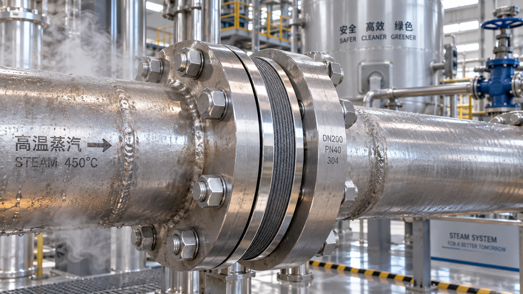
A steam leak at a flanged joint rarely begins with one obvious mistake. More often, it develops from a chain of reasonable but incomplete decisions: a gasket selected only by its published temperature limit, a flange surface assumed to be acceptable, bolts tightened without considering relaxation, or a shutdown cycle treated as a routine event rather than a severe mechanical test.
Selecting high temperature gaskets for steam service, flanged joints, and repeated thermal cycling requires more than matching a material to a maximum temperature rating. Technical evaluators need to consider the full sealing system: process medium, pressure and temperature profile, flange rigidity, surface finish, available bolt load, installation method, and the number and severity of thermal cycles. The objective is not simply to install a gasket that survives heat. It is to maintain sufficient sealing stress throughout operation without damaging the flange, overstressing bolts, or creating an avoidable maintenance burden.
For EPC teams, plant reliability engineers, and procurement specialists, the right specification begins by turning operating conditions into a realistic joint model. This guide provides a practical framework for making that decision.
Start with the Service Profile, Not the Catalogue Temperature
Material data sheets often present a single upper temperature figure. That figure can be useful, but it is not a complete service rating. A gasket may tolerate a certain temperature in air, for example, while performing very differently in saturated steam, superheated steam, oxygen-bearing process gas, condensate, or a chemically contaminated line.
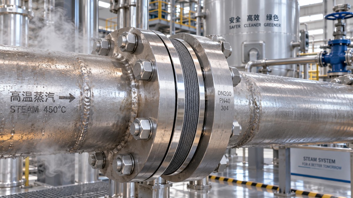
Steam service is particularly demanding because it combines elevated temperature, pressure, moisture, and frequent changes in operating state. During startup, the joint may move from ambient conditions to operating temperature quickly. During shutdown, condensate can form. If the line experiences intermittent operation, the gasket and bolts repeatedly expand and contract at different rates. Each event can reduce the contact stress needed for a tight seal.
Before comparing gasket families, define the actual duty point with enough precision to reveal its risks:
- Normal operating temperature and pressure, plus credible startup, upset, and shutdown conditions.
- Whether the steam is saturated, superheated, wet, contaminated, or carries treatment chemicals.
- Pressure class, line size, flange type, facing geometry, and joint orientation.
- Expected thermal ramp rate and the frequency of heat-up/cool-down cycles.
- Potential vibration, pipe movement, external loads, or misalignment.
- Maintenance access, required leakage performance, and consequences of a release.
A gasket that appears suitable at steady-state temperature may not retain enough compressive stress after repeated cycling. Conversely, a more robust material will not compensate for a weak flange, insufficient bolt capacity, or a damaged sealing face. Selection has to treat the joint as a system.
Why Thermal Cycling Changes the Evaluation
Thermal cycling is not merely a temperature variation on a process datasheet. It changes the mechanics of the bolted joint. Flanges, bolts, and gaskets are made from different materials, have different cross-sections, and heat at different rates. As temperature rises, joint components expand unevenly. As they cool, the original stress distribution may not return.
Some gasket materials exhibit stress relaxation or creep at elevated temperature. In practical terms, the gasket may gradually lose thickness under load, reducing the bolt tension transferred into the sealing interface. Bolt relaxation can contribute as well. Once contact pressure falls below the level required to resist internal pressure and fluid penetration, leakage may begin—even when the gasket itself looks intact after disassembly.
For cycling applications, evaluate more than compressibility. Ask how well the material retains load, recovers after unloading, resists oxidation or thermal degradation, and accommodates limited flange movement. A gasket designed for conformability may be attractive on imperfect faces, yet its long-term stress retention may be less suitable for a demanding high-temperature steam line. A denser, more stable gasket may offer better durability but demand higher, more controlled bolt load.
Match the Gasket Family to the Joint’s Real Constraints
There is no universal “best” high-temperature gasket. The appropriate construction depends on service conditions and, equally important, on what the joint can reliably deliver.
Compressed fiber and non-asbestos sheet materials
Modern non-asbestos sheet gaskets are widely used across general industrial services because they are easy to cut, economical, and forgiving of moderate flange irregularities. Certain grades are formulated for elevated-temperature service, but selection should be conservative in steam applications, especially where temperature and pressure are both high or where cycling is frequent. Their performance depends heavily on binder system, reinforcement, thickness, and sustained bolt load.
These materials may be appropriate for lower-to-moderate duty services where the supplier’s published operating envelope supports the exact steam condition and where installation control is reliable. They are less likely to be the preferred choice when prolonged high-temperature exposure and repeated startups create a significant relaxation risk.
Expanded graphite sheet and graphite-based constructions
Graphite is valued in high-temperature gasket applications for its thermal stability, chemical resistance across many industrial media, and ability to conform to flange surfaces. Graphite sheet gaskets, often reinforced with metallic inserts or tangs for handling strength, are common candidates for steam and thermal cycling duties.
However, graphite is not a simple default. Oxidizing environments, purity requirements, handling damage, and flange finish all deserve attention. Reinforced grades may improve mechanical integrity, while the gasket thickness and density influence both conformability and required seating stress. Ensure that the selected graphite construction is qualified for the actual medium and environmental exposure rather than relying on the base material name alone.
Spiral wound gaskets
For raised-face flanges in demanding pressure-temperature service, spiral wound gaskets are often selected because their layered metal-and-filler construction can provide resilient sealing behavior. Commonly used with graphite filler for high-temperature steam, they are available with inner and outer rings that support centering, control compression, and improve radial stability.
The metal winding must be compatible with the service environment and flange material. Ring configuration also matters. An inner ring can help prevent inward buckling and reduce turbulence-related erosion in certain services, while an outer ring assists alignment and helps limit over-compression. Spiral wound gaskets require proper flange geometry and controlled bolting; they are not forgiving of severe flange damage or poor installation practice.
Metal-jacketed, corrugated, and solid metal solutions
Metallic gasket designs may be considered when temperature, pressure, mechanical durability, or fire-resistance requirements exceed the practical limits of softer materials. Their performance can be excellent in properly engineered joints, but they generally demand better flange finish, greater bolt load, and tighter dimensional control. A solid metal gasket, in particular, is not a casual substitute for a softer design. Without sufficient seating stress and compatible flange faces, it can leak or damage the joint.
Read the Flange Before Specifying the Gasket
The gasket cannot be evaluated independently from the flange. A technically capable material can fail early if installed between warped faces, deeply scored serrations, corroded seating lands, or mismatched flange types. During a turnaround, assess the joint rather than assuming its nominal standard dimensions tell the full story.
Check flange facing type, width, flatness, surface finish, corrosion, radial scoring, and evidence of previous gasket extrusion. Raised-face, flat-face, ring-type joint, tongue-and-groove, and male-female flanges impose different containment and seating conditions. A gasket designed for one facing arrangement should not be adapted casually to another.
Flange rotation is another overlooked factor. Under bolt load, a flange can bend slightly, reducing compression near the inside diameter or creating uneven stress across the sealing surface. Thin, low-rigidity flanges and joints exposed to external piping loads deserve particular scrutiny. If calculations or field evidence indicate excessive rotation, a gasket upgrade alone may not cure the issue. The corrective action may involve flange redesign, additional support, revised bolting, or load-control measures.
Bolt Load Is the Deciding Variable Many Specifications Miss
Every gasket has a practical seating window. Too little bolt load leaves pathways for steam to escape. Too much can crush a soft gasket, damage a winding, distort flange faces, or drive the gasket beyond its recovery range. The required load must be achievable with the installed studs, nuts, flange geometry, lubrication practice, and tightening procedure.
Technical evaluators should request gasket stress data and use an applicable design methodology for the project. Depending on the jurisdiction and equipment type, this may involve ASME-based flange design practices, EN 1591 methods, or another recognized engineering approach. Published values should be treated as inputs to joint design, not as a replacement for it.
Field installation is where calculated capacity can disappear. Uneven torque, dirty threads, inconsistent lubricant, incorrect tightening sequence, or an uncalibrated tool can create large differences in actual bolt tension. For critical steam joints, specify a documented tightening procedure. Multi-pass cross-pattern tightening, controlled final loading, and verification with suitable tensioning or torque tools are often more valuable than simply increasing torque.
Questions to Put to Suppliers During Technical Evaluation
A useful gasket submittal should support engineering judgment rather than simply list broad material claims. Ask the supplier to address the exact service medium, continuous and transient temperatures, pressure, flange standard, facing type, gasket dimensions, and anticipated cycling profile.
- What is the recommended operating range for this specific construction in the stated steam condition?
- What minimum and maximum gasket stress should be maintained during installation and operation?
- How does the material behave under elevated-temperature stress relaxation or cyclic exposure?
- Which winding metal, filler, reinforcement, and ring materials are proposed, and why?
- What flange surface finish and flatness conditions are recommended?
- Is the proposed gasket compatible with the relevant flange standard and required emissions or leakage criteria?
- Are installation instructions, lot traceability, and material documentation available for the supplied product?
Where the service is safety-critical or shutdown costs are substantial, require evidence relevant to the proposed duty. A generic laboratory result may not represent a cycling steam application. Qualification records, recognized test methods, and documented service experience are more useful when their limits and test conditions are clearly stated.
Common Selection Errors That Create Repeat Leaks
Choosing by peak temperature alone. A maximum temperature figure ignores pressure, oxidizing conditions, steam quality, load retention, and cycling. It is a screening value, not a final approval.
Using a thicker gasket to hide flange problems. Greater thickness can help accommodate minor imperfections, but it can also increase relaxation and require more bolt travel. Investigate damaged or distorted flange faces instead of expecting the gasket to solve a mechanical defect.
Replacing like-for-like without reviewing the failure mode. If a previous gasket leaked after several cycles, the problem may be bolt load loss, flange rotation, incorrect gasket compression, or pipe strain. Reordering the same part preserves the same failure path.
Mixing components without design review. Changing filler, winding alloy, ring style, bolt lubricant, stud grade, or gasket thickness can materially alter joint behavior. Treat each change as an engineering modification, particularly in high-energy steam service.
Ignoring storage and handling. Graphite, sheet, and spiral wound gaskets can be damaged before installation. Keep them clean, dry, flat where appropriate, and protected from bending, impact, and unauthorized reuse. A removed gasket should generally not be reinstalled.
A Practical Approval Path for High Temperature Gaskets
For a new specification or a persistent leak problem, start with a joint dossier rather than a product shortlist. Gather process data, line drawings, flange details, previous gasket records, bolt information, installation history, and inspection findings. This creates a factual basis for comparing options.
Next, identify the dominant risk: sustained temperature, rapid cycling, low available bolt load, flange degradation, chemical exposure, or leakage sensitivity. Select gasket constructions that address that risk without introducing a new mismatch. Then confirm that the flange and bolting system can deliver the required seating and operating load.
Finally, turn the selection into an executable maintenance instruction. State the gasket identification, dimensions, material construction, ring configuration if applicable, flange preparation requirements, approved lubricant, tightening sequence, target loading method, and inspection hold points. A reliable gasket design can still fail if the final work package leaves critical installation decisions to guesswork.
For steam lines and other thermally active systems, gasket selection is a reliability decision with consequences beyond the joint itself. The strongest specification connects material behavior to real operating conditions and gives field teams a clear route to achieve the intended seal. That discipline is what separates a gasket that merely fits from one that remains dependable through the next startup, the next shutdown, and the many cycles in between.
Technical Specifications
- Selecting High-Temperature Gaskets for Steam, Flanges, and Thermal CyclingAuthor :Heavy Industry Strategist
- How to Select an Emissions Monitoring System Analyzer for Compliance ReportingAuthor :Precision Metrology Expert
- How to Select an Access Control Management System for Multi-Site FacilitiesAuthor :Safety Compliance Lead
Expert Insights

Chief Security Architect
Dr. Thorne specializes in the intersection of structural engineering and digital resilience. He has advised three G7 governments on industrial infrastructure security.
Related Analysis
- Sep 22, 2026Selecting High-Temperature Gaskets for Steam, Flanges, and Thermal CyclingAuthor :Heavy Industry Strategist
- Sep 21, 2026How to Select an Emissions Monitoring System Analyzer for Compliance ReportingAuthor :Precision Metrology Expert
- Sep 20, 2026How to Select an Access Control Management System for Multi-Site FacilitiesAuthor :Safety Compliance Lead
Core Sector // 01
Security & Safety
- Selecting High-Temperature Gaskets for Steam, Flanges, and Thermal CyclingAuthor :Heavy Industry Strategist

- Selecting Low-Friction Pneumatic Seals for High-Cycle, Low-Pressure CylindersAuthor :Heavy Industry Strategist

- Selecting Spherical Roller Bearings for Mining: Load, Contamination, and Service LifeAuthor :Heavy Industry Strategist

- Do Deep Groove Ball Bearings Need Special Seals in Coastal Humidity?Author :Heavy Industry Strategist

- How to Select Anti Vibration Rubber Shock Absorbers for Machinery and EquipmentAuthor :Heavy Industry Strategist

- When to Specify Induction Hardened Slewing Ring Bearings for Heavy-Duty EquipmentAuthor :Heavy Industry Strategist

- How to Evaluate Weather Resistant EPDM Extrusion for Outdoor Sealing ApplicationsAuthor :Heavy Industry Strategist

- Bearing and Seal Lead Times Stretch to 22 WeeksAuthor :Heavy Industry Strategist