Choosing Flexible PVC Copper Wire: Size, Voltage and Temperature Ratings
Author
Date Published
Reading Time
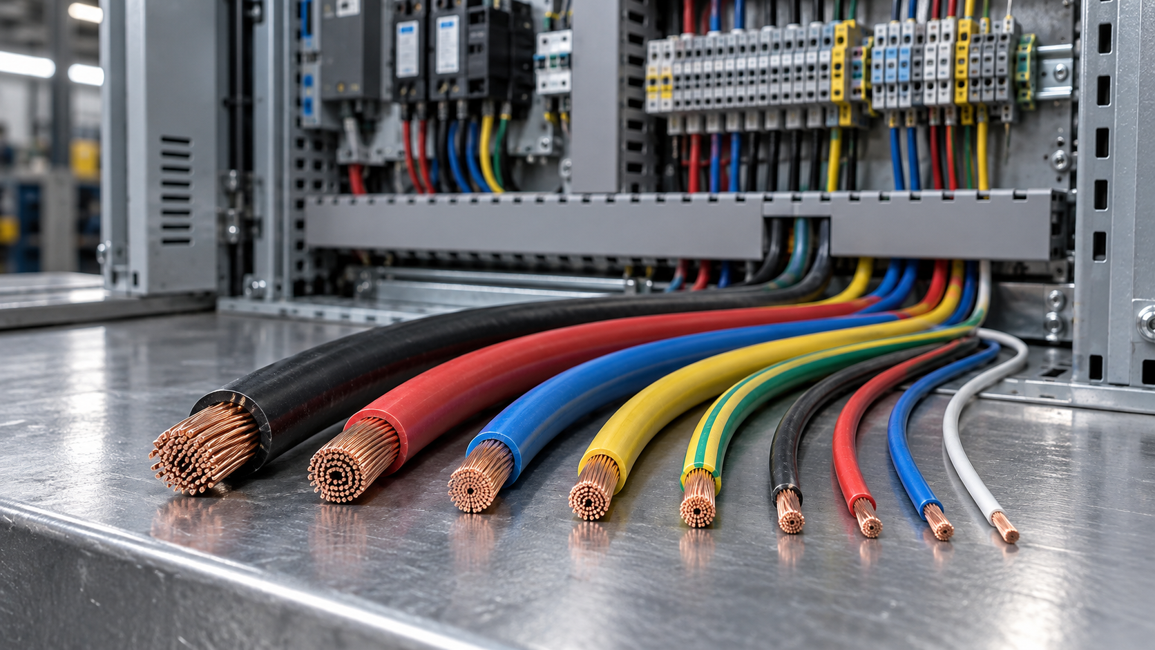
A flexible copper conductor may look like a straightforward purchase until two apparently similar wires arrive with different voltage markings, temperature limits and strand constructions. One may be suitable for a control panel; the other may be intended for a different installation entirely. Choosing between them on conductor size alone can leave an evaluator with a specification that looks right on paper but does not fit the operating conditions.
Selecting flexible PVC copper wire requires a combined assessment of electrical load, voltage, temperature, installation method and applicable standards. This guide sets out how those factors interact, what to ask a supplier and where a seemingly acceptable choice can fall short.
Start with the installation, not the catalog
Before comparing wire sizes, establish what the conductor will actually do. Is it internal wiring inside a machine, a connection within a control cabinet, or part of a flexible cable feeding movable equipment? Will it carry a continuous load, an intermittent signal or motor current? The answers shape both the required construction and the evidence needed to approve it.
Record the expected circuit voltage, design current, ambient temperature, installation route and required service life. Include practical details such as enclosure heat, proximity to hot surfaces, cable grouping, exposure to oil or cleaning agents, and whether the wire will be stationary after installation.
That last distinction matters. A finely stranded conductor is easier to route than a solid one, but “flexible” does not automatically mean suitable for repeated bending. A wire designed for occasional movement during assembly may not withstand continuous travel in a cable carrier. Repeated-motion applications need a construction and test evidence appropriate to that duty.
Choosing conductor size: current capacity is only the beginning
Conductor size is commonly expressed as nominal cross-sectional area in square millimeters or as an American Wire Gauge number. Cross-sectional area affects resistance and heat generation, but it does not determine a wire’s allowable current in isolation.
Two wires with the same nominal copper area can have different permitted current-carrying capacities when their insulation temperature ratings, installation methods or surrounding conditions differ. A conductor in free air does not dissipate heat in the same way as one packed into a conduit with several loaded circuits.
Check current against the actual installation
Use the ampacity tables and correction factors required by the installation code applicable to the project. Depending on the system, the assessment may need to account for:
- Ambient temperature around the installed wire, including elevated enclosure temperatures.
- The number of loaded conductors grouped together and their arrangement.
- Whether the route is enclosed, insulated, ventilated or exposed to other heat sources.
- The conductor and insulation temperature limits, as well as terminal ratings.
- Continuous loading requirements and the operating characteristics of the connected equipment.
Do not assume that a manufacturer’s current value applies to every installation. Check the conditions behind it. A rating based on a single conductor in free air may not be appropriate for a tightly filled cabinet duct.
Verify voltage drop and fault performance
A wire that passes an ampacity check may still be too small for a long run. Voltage drop depends on conductor impedance, circuit length, load current and the circuit arrangement. Excessive drop can affect equipment operation, particularly where starting current or voltage-sensitive loads are involved. Use the calculation method and limits applicable to the installation; for AC circuits, consider reactance and power factor where relevant.
Also check whether the conductor and its protective device can withstand and clear prospective fault conditions as required by the governing rules. Protection coordination is a system question, not a wire-label question. A larger conductor chosen to reduce voltage drop should still be checked for terminal compatibility and the required overcurrent protection.
Understand what the voltage rating covers
The voltage marking relates to the wire’s insulation system and the conditions defined by its product standard. It is not a recommendation to operate every circuit at that value, nor is it evidence that the wire is suitable for every location.
For example, a wire marked 300/500 V uses a rating convention in which the first value generally denotes rated voltage to earth and the second denotes voltage between conductors. Confirm the meaning against the relevant product standard, especially when comparing IEC-style designations with products marked under a different certification system.
Compare the wire’s rated voltage with the circuit and installation requirements, including the supply arrangement and any applicable rules for control circuits. Consider expected transients and equipment-specific requirements as well: a nominal voltage comparison alone may not address the stresses associated with a particular drive or switching application.
Finally, distinguish a conductor from a complete cable assembly. A single insulated wire’s voltage marking does not automatically establish that an assembled multicore cable, connector system or installation has the same suitability. The surrounding construction and applicable approvals must also be assessed.
Temperature ratings: identify the weakest limit
PVC insulation has a defined temperature rating, but that number should be read alongside the conditions and duration for which it applies. A continuous operating temperature, a short-term overload limit and a short-circuit temperature are not interchangeable. Check which rating the manufacturer declares and which product standard governs it.
The conductor runs hotter than the surrounding air when it carries current. Heat from neighboring circuits, equipment and sunlight can add to that rise. If the insulation is rated for a higher temperature than the connected terminal, the terminal may still limit the allowable current or require a different sizing method under the applicable code.
Cold conditions deserve attention too. PVC formulations vary, and an acceptable minimum temperature for a fixed installation is not necessarily an acceptable temperature for bending during installation or movement in service. Ask for both limits when cold handling or outdoor maintenance is foreseeable.
Temperature also affects the choice of material. If the route involves sustained heat, frequent temperature cycling or harsh chemical exposure beyond the stated PVC properties, changing the insulation system or cable construction may be more appropriate than simply increasing conductor size.
Compare flexible PVC copper wire on a like-for-like basis
A datasheet comparison is most useful when it separates verified properties from assumptions. The following checks help evaluators identify products that only appear equivalent.
For conductor construction, IEC 60228 defines classes for stranded conductors, including flexible classes. Class 5 and Class 6 descriptions are useful comparison points, but strand class alone does not certify cable-carrier performance. Request the manufacturer’s bending guidance and any relevant dynamic-flex test data for the complete product.
Check termination hardware early. Fine-stranded conductors may require terminals, ferrules or preparation methods specified by the terminal manufacturer and installation rules. An otherwise suitable wire can become difficult to approve if its diameter or strand construction does not match the selected connector.
Match the standard to the market and the application
There is no single approval that makes every flexible PVC wire acceptable everywhere. The applicable product standard, installation code and certification requirements depend on the destination market and intended use. IEC 60228 concerns conductor characteristics; other standards address particular wire types and their construction or tests. In North American projects, the required UL wire type or other listing may depend on the equipment and installation.
CE marking should not be treated as a universal wire certification or a substitute for checking the legislation and conformity documents relevant to the product. Likewise, an ISO management-system certificate describes a management system; by itself, it does not prove that a specific wire meets an electrical product standard.
Ask the supplier for documentation tied to the exact part number: the product datasheet, applicable standard designation, declaration or certification where required, and traceable test information. Review the scope and validity of any third-party listing through the issuing organization’s available records. If a specification calls for flame performance, oil resistance or another property, identify the actual test method and acceptance criteria rather than relying on a broad marketing description.
A practical evaluation: a warm, crowded control cabinet
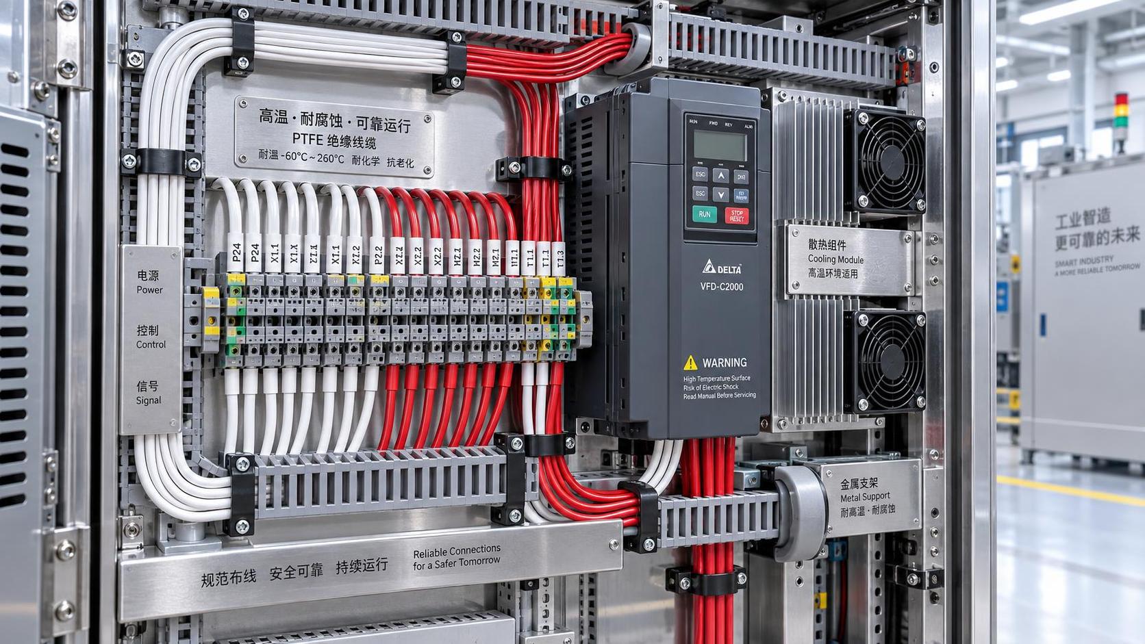
Consider a flexible wire being selected for a continuously loaded circuit inside a control cabinet. The evaluator has the circuit current and supply voltage, but the route passes through a duct containing several other loaded conductors. The cabinet’s internal temperature can also be higher than the room temperature used in the initial estimate.
The appropriate response is not simply to select the next larger size. Establish the design conditions, then apply the relevant ampacity method and correction factors for the installation. Check the resulting conductor against voltage-drop requirements, protective-device selection and the temperature ratings of both wire and terminals. Confirm that the chosen insulation voltage rating and wire type are acceptable for the circuit and destination market.
Before approval, compare the wire’s outside diameter with duct fill and terminal capacity. If the cabinet door moves the wire during normal operation, review the bend route and movement duty separately. This sequence may confirm the original size, require a larger conductor or reveal that a different construction is needed. The point is to make the decision traceable rather than rely on a single catalog number.
Questions to resolve before releasing the specification
- What are the normal and worst-case current, voltage and ambient conditions?
- Which installation code and product standard apply in the destination market?
- Have grouping, enclosure heat and other applicable ampacity corrections been included?
- Are voltage drop, fault conditions and protective-device coordination acceptable?
- Is the wire fixed after installation, occasionally moved or continuously flexed?
- Are the insulation, minimum bend temperature and environmental resistance suitable for the route?
- Do the conductor construction, overall diameter and temperature rating match the terminals?
- Does the supporting documentation identify the exact product and required properties?
A defensible choice brings all of these checks together. The best-fit wire is not necessarily the one with the highest temperature marking or the largest conductor; it is the one whose verified construction and ratings meet the complete installation requirement. Keep the assumptions and supporting documents with the specification so that future substitutions can be evaluated against the same conditions.
Technical Specifications
Expert Insights

Chief Security Architect
Dr. Thorne specializes in the intersection of structural engineering and digital resilience. He has advised three G7 governments on industrial infrastructure security.
Related Analysis
- Nov 01, 2026Manufacturing Overtakes Construction in China's Steel ConsumptionAuthor :
- Nov 01, 2026Choosing Flexible PVC Copper Wire: Size, Voltage and Temperature RatingsAuthor :Grid Infrastructure Analyst
- Oct 31, 2026FCC Votes to Bar All China-Based Labs From Testing Electronics for US MarketAuthor :Precision Metrology Expert
Core Sector // 01
Security & Safety
- Choosing Flexible PVC Copper Wire: Size, Voltage and Temperature RatingsAuthor :Grid Infrastructure Analyst

- Choosing an XLPE Power Cable Supplier: Test Reports, Traceability, and Lead TimesAuthor :Grid Infrastructure Analyst

- How to Select XLPO Insulated Solar Cable for UV, Heat, and High-Voltage PV SystemsAuthor :Grid Infrastructure Analyst

- Selecting PTFE Insulated Hookup Wire for High-Temperature Control PanelsAuthor :Grid Infrastructure Analyst

- How Contractors Can Evaluate EPC Sourcing Solutions for Cost, Lead Time, and RiskAuthor :Grid Infrastructure Analyst

- What Drives Silicone Cable Bulk Price in Industrial Orders?Author :Grid Infrastructure Analyst

- EN 61000-6-4:2026 Takes Effect for EU-Bound ControlsAuthor :Grid Infrastructure Analyst

- How to Choose Low Smoke Cables and Wiring for Safer Commercial Buildings?Author :Grid Infrastructure Analyst