Selecting Low-Friction Pneumatic Seals for High-Cycle, Low-Pressure Cylinders
Author
Date Published
Reading Time
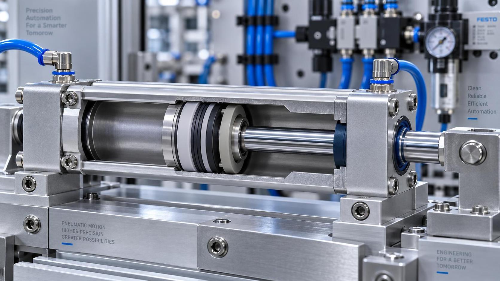
For a high-cycle cylinder running at low pressure, the lowest catalog friction value is not automatically the right choice. The seal must still maintain contact when pressure is weak, survive frequent reversals, tolerate real guide and bore conditions, and avoid unstable motion at the start of each stroke. A seal that moves freely on a laboratory fixture but permits intermittent leakage or wears quickly in production creates a larger problem than a slightly higher-friction design.
When selecting low friction pneumatic seals, evaluate the complete motion system: available pressure, load direction, cycle profile, rod or piston speed, surface finish, lubrication strategy, and contamination exposure. The practical goal is not minimum friction in isolation. It is repeatable breakaway behavior, smooth running force, controlled air loss, and a service interval that fits the equipment.
Start with the cylinder’s force margin
Low-pressure pneumatic applications have limited force available to overcome seal drag, guide friction, external load, and any side loading introduced by the mechanism. This makes seal selection more sensitive than it is in a cylinder supplied at higher pressure.
Begin by calculating the usable force margin across the operating pressure range, not only at nominal supply pressure. Consider pressure losses through valves, fittings, regulators, and tubing during fast cycles. A cylinder may appear adequately sized at a steady supply condition, then hesitate at stroke initiation when several actuators move at once.
Breakaway friction deserves special attention. Static friction is typically higher than running friction, so a seal can produce a visible stick-slip event even when the average running force looks acceptable. In pick-and-place units, light clamping functions, indexing devices, and test fixtures, this often appears as delayed motion followed by a sudden jump. The issue may be incorrectly attributed to valve response or controller timing when the seal and cylinder force balance are the underlying cause.
Ask suppliers for force-versus-pressure information where available, but use it as a screening input rather than a final answer. Seal drag is affected by the actual bore, rod condition, temperature, lubricant, assembly compression, and break-in behavior. A representative cylinder test remains more useful than a friction figure detached from its test conditions.
Choose the sealing concept before choosing the compound
Material matters, but geometry and energization method often determine whether a low-friction design will work at low pressure. The main question is how the seal maintains reliable contact with the moving surface while keeping drag controlled.
A pressure-energized lip can seal effectively once pressure is established, yet be less forgiving when the cylinder must hold position or begin moving at very low differential pressure. A mechanically preloaded design may provide better low-pressure sealing, but that preload adds friction. The preferred design is usually the one that applies only as much contact force as the real duty requires.
For double-acting cylinders, assess both directions separately. Extension and retraction may have different effective areas, loads, speeds, and back-pressure conditions. A seal package that performs well in one direction can produce poorer behavior in the other, particularly where exhaust restrictions are used to control speed.
Low friction cannot compensate for poor mechanical support
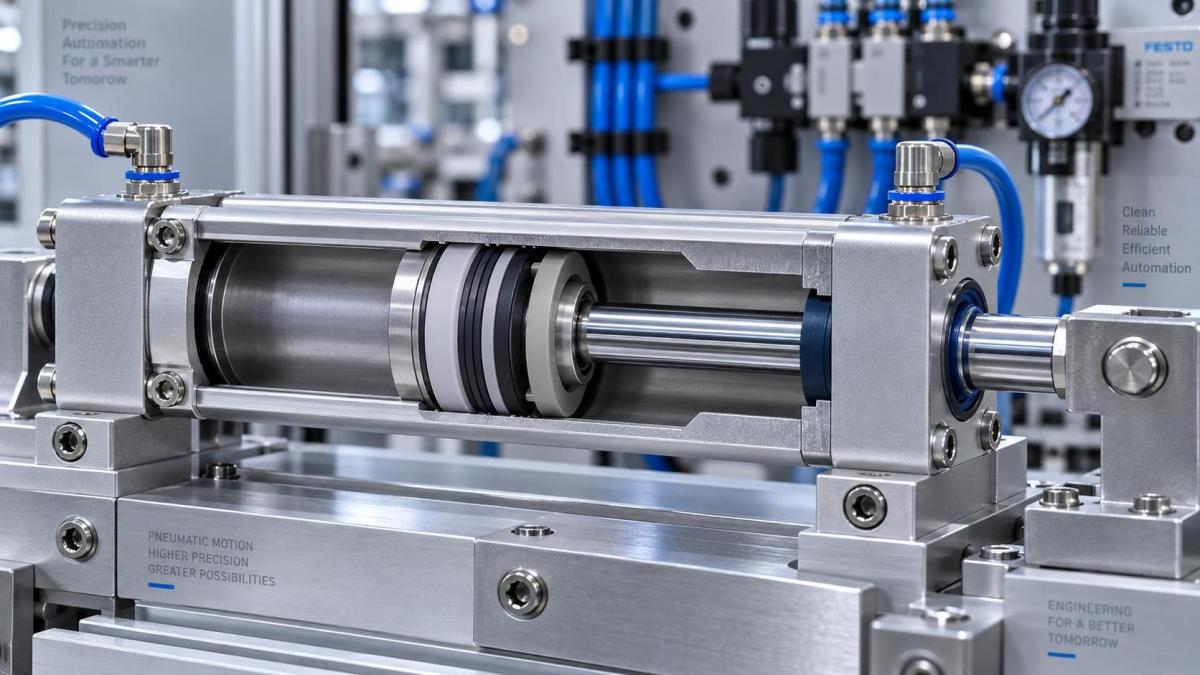
Seal wear is frequently treated as a compound problem when it is actually a guidance problem. Side load, rod bending, off-axis mounting, or an inadequate bearing length forces the seal lip against one side of the rod or bore. Friction rises, wear becomes uneven, and leakage follows. Specifying an even lower-drag seal may reduce the symptom briefly without correcting the contact pattern causing it.
Review the cylinder arrangement as part of the seal decision:
- Confirm that the rod, piston, and load path are aligned throughout the stroke.
- Check whether external guides carry the process load or whether the cylinder itself is being asked to guide it.
- Examine bearing band condition, piston clearance, and rod straightness on existing assemblies.
- Match seal geometry to the actual bore and rod surface quality, including plating condition and directional finishing marks.
- Consider end-of-stroke impact, because repeated impact can deform lips, damage energizers, and accelerate extrusion-related wear.
High cycle count magnifies small installation errors. A sharp lead-in edge can nick a low-drag sealing lip during assembly. A poorly cleaned groove can prevent the seal from seating evenly. Excessive stretch or compression changes the contact load before the cylinder ever enters service. These faults can make two nominally identical cylinders behave very differently.
Match materials to air quality and lubrication reality
Technical evaluations often begin with the assumption that compressed air is clean and stable. In service, air may carry water, oil aerosol, cleaning residues, fine particles, or intermittent lubricant from upstream equipment. These conditions can change both friction and seal life.
A dry-running cylinder needs a seal designed for dry operation against the specified surface materials. Adding oil later may alter friction, swell some elastomer formulations, or collect debris. Conversely, a seal system intended for lubricated service may not retain the same wear behavior after lubrication is removed. The operating policy should be decided before finalizing the seal material, rather than treating lubrication as a maintenance preference.
Elastomer selection should also reflect temperature range and chemical exposure from washdown, nearby process fluids, or cleaning agents. Material compatibility is not only about catastrophic attack. Gradual hardening, softening, or loss of resilience can increase breakaway force long before visible leakage occurs.
In dusty or abrasive environments, the rod-side exclusion strategy deserves as much attention as the pressure seal. A low-friction rod seal can be damaged by contaminants carried into the cylinder. Wipers, protective bellows, rod orientation, and maintenance access may provide more value than choosing a more exotic seal compound.
Define what “high cycle” means in the actual duty
Cycle count alone is incomplete. A short, rapid reciprocating stroke creates a different seal demand from a long stroke with dwell periods. Frequent reversals stress the seal’s ability to transition smoothly through zero speed. Long dwell periods can allow contact surfaces to settle, increasing the breakaway event at the next command. High speed may generate more heat and expose lubrication limitations, while low speed makes stick-slip more visible.
Build a duty profile that includes stroke length, cycles per shift, speed range, reversal frequency, dwell time, temperature, supply-pressure variation, and whether the actuator must hold a position without continuous pressure. This profile helps distinguish a seal suitable for general pneumatic motion from one suited to precision, high-repetition equipment.
Air consumption is also part of the decision. Internal leakage can force more frequent valve compensation and reduce repeatability, but excessive seal preload creates its own energy penalty by demanding higher pressure to achieve the same motion. The best balance is application-specific: enough sealing stability to avoid meaningful pressure loss, with drag low enough to preserve force margin and consistent cycling.
Test the candidate seal package in a representative assembly
Bench screening should reproduce the conditions most likely to expose failure: low supply pressure, realistic load, normal stroke speed, expected dwell, and repeated reversals. Testing only at a comfortable pressure can conceal poor low-pressure start behavior. Testing only a new cylinder can conceal sensitivity to ordinary production variation.
A practical verification plan should observe more than leakage. Track the pressure at which motion begins, the consistency of stroke time, movement smoothness near reversal, visible rod-film condition, and any change in performance after sustained cycling. Inspect the seal, bore, rod, and bearing surfaces together. A worn lip without damage elsewhere suggests one set of causes; localized scoring or asymmetric wear points toward alignment, contamination, or surface defects.
It is also useful to compare candidates after realistic stop-start periods. A seal that runs smoothly in continuous cycling may behave differently after equipment downtime, when static contact and lubricant distribution have changed.
Common selection mistakes that create avoidable problems
Specifying only “low friction.” This description does not define the pressure range, seal configuration, motion direction, lubricant condition, or acceptable leakage behavior. It leaves too much interpretation to the supplier and makes comparison difficult.
Using a catalog value as a system prediction. Published friction data can be useful, but it is tied to a particular test method and geometry. It cannot fully represent a cylinder with a different bore finish, mounting condition, or load.
Ignoring gland and installation design. A suitable material in an incorrect groove will not behave like the catalog sample. Compression, clearance, lead-in geometry, and support all influence drag and sealing stability.
Replacing seals without examining guides and surfaces. When leakage repeatedly returns in one location, investigate mechanical causes before changing to a harder or tighter seal. That approach often increases friction without resolving the wear mechanism.
Combining incompatible lubrication practices. A transition from lubricated to dry air, or the addition of an unplanned oil source, should be evaluated as a system change rather than a minor maintenance adjustment.
A concise procurement specification improves supplier comparison
For meaningful quotations and technical reviews, provide the cylinder bore and rod dimensions, seal location, pressure range, air treatment, lubricant policy, temperature exposure, stroke and cycle profile, speed range, external loading, mounting arrangement, surface materials, and the failure mode being avoided. State whether the priority is lower breakaway force, reduced running drag, improved low-pressure sealing, longer wear life, or a controlled balance among them.
Global Industrial Core’s approach to mechanical-component sourcing is useful here: evaluate the seal as a verified part of a functional assembly, not as an isolated consumable. Documentation should connect the proposed profile and material to the cylinder geometry, operating medium, and inspection criteria. That makes technical comparison clearer and reduces the chance of selecting a low-drag component that is unsuitable for the actual cylinder.
The strongest selection decision is usually the least dramatic one: a seal design with stable low-pressure contact, manageable breakaway force, compatible materials, proper guidance, and evidence from a representative operating cycle. That combination is what keeps a high-cycle pneumatic cylinder responsive after the initial installation period has passed.
Technical Specifications
- How to Select Electronic Hotel Key Card Locks for Guest Rooms and Staff AreasAuthor :Safety Compliance Lead
- How to Select Lab Instruments for Reliable Chemical Analysis WorkflowsAuthor :Precision Metrology Expert
- How to Size a UPS for Server Rooms: Load, Runtime, and Redundancy FactorsAuthor :Grid Infrastructure Analyst
Expert Insights

Chief Security Architect
Dr. Thorne specializes in the intersection of structural engineering and digital resilience. He has advised three G7 governments on industrial infrastructure security.
Related Analysis
- Sep 17, 2026How to Select Electronic Hotel Key Card Locks for Guest Rooms and Staff AreasAuthor :Safety Compliance Lead
- Sep 16, 2026How to Select Lab Instruments for Reliable Chemical Analysis WorkflowsAuthor :Precision Metrology Expert
- Sep 15, 2026How to Size a UPS for Server Rooms: Load, Runtime, and Redundancy FactorsAuthor :Grid Infrastructure Analyst
Core Sector // 01
Security & Safety
- Selecting Low-Friction Pneumatic Seals for High-Cycle, Low-Pressure CylindersAuthor :Heavy Industry Strategist

- Selecting Spherical Roller Bearings for Mining: Load, Contamination, and Service LifeAuthor :Heavy Industry Strategist

- Do Deep Groove Ball Bearings Need Special Seals in Coastal Humidity?Author :Heavy Industry Strategist

- How to Select Anti Vibration Rubber Shock Absorbers for Machinery and EquipmentAuthor :Heavy Industry Strategist

- When to Specify Induction Hardened Slewing Ring Bearings for Heavy-Duty EquipmentAuthor :Heavy Industry Strategist

- How to Evaluate Weather Resistant EPDM Extrusion for Outdoor Sealing ApplicationsAuthor :Heavy Industry Strategist

- Bearing and Seal Lead Times Stretch to 22 WeeksAuthor :Heavy Industry Strategist

- Angular Contact Ball Bearings Explained: Contact Angle, Load Capacity, and Common UsesAuthor :Heavy Industry Strategist