How to Select Process Control Instruments for Accuracy, Safety, and Uptime
Author
Date Published
Reading Time
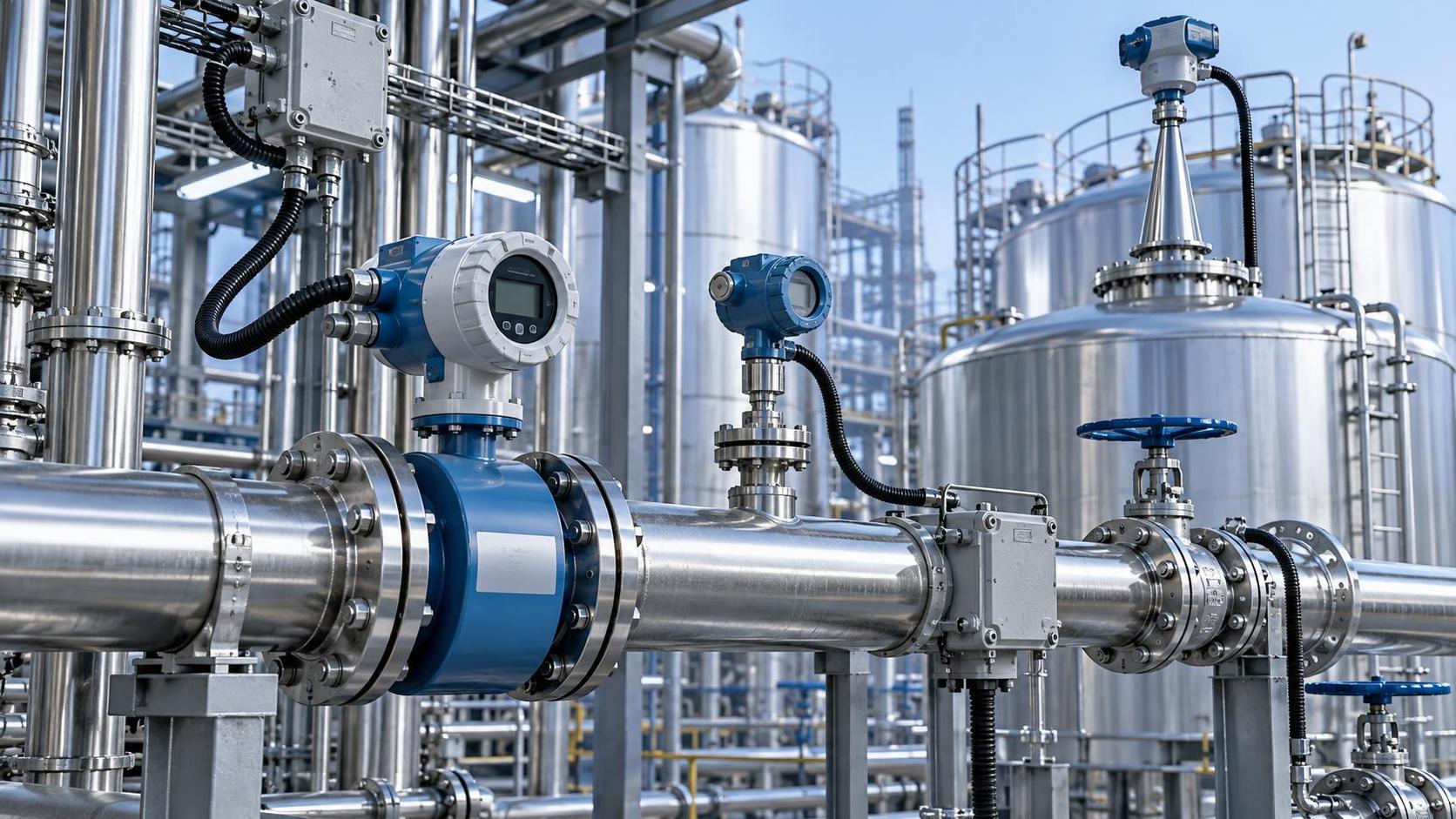
Selecting industrial instruments for process control is a critical engineering decision that reaches far beyond a datasheet comparison. A transmitter that drifts under temperature cycling, a flowmeter installed with inadequate straight run, or a level device chosen without regard for foam can quietly erode measurement confidence long before it causes an obvious alarm. In a high-consequence facility, those small uncertainties can affect product quality, safety margins, maintenance workload, regulatory reporting, and ultimately plant availability.
For technical evaluators, the goal is not to find the instrument with the longest feature list. It is to select a measurement solution that remains credible in the real process: during startup, upset conditions, seasonal changes, washdowns, power interruptions, and years of service. The strongest selection decisions connect process physics, installation reality, functional safety, communications architecture, and lifecycle support into one evaluation.
Start with the Decision the Measurement Must Support
Before comparing models, define what the measurement is expected to do. The same pressure reading may be used for routine trend monitoring in one loop, control-valve positioning in another, and high-pressure trip protection in a third. These duties demand different levels of accuracy, response time, diagnostics, redundancy, and proof-test discipline.
A useful first question is: What happens if this reading is wrong, late, or unavailable? The answer establishes the required level of engineering rigor. A noncritical utility indication may tolerate a modest uncertainty and a manual fallback. A boiler drum level signal, reactor pressure input, custody-transfer flow measurement, or emissions-monitoring point may require a much more formal approach to uncertainty, traceability, verification, and failure response.
Build the instrument requirement around the decision rather than around a familiar product category. Document the following before issuing an RFQ:
- The measured variable and expected operating, minimum, maximum, and abnormal ranges.
- The control or protection function that depends on the signal.
- Required accuracy at the actual operating point, not only at full scale.
- Required response time, update rate, and acceptable signal latency.
- Consequences of high, low, frozen, noisy, or missing readings.
- Whether the instrument is part of a basic process control system, an alarm function, or a safety instrumented function.
This framing prevents a frequent procurement error: choosing a technically capable device that is misaligned with the loop’s true risk and performance requirement.
Translate Process Conditions into a Measurement Principle
Industrial instruments for process control are not interchangeable sensors in different housings. Measurement principles respond differently to density changes, conductivity, entrained gas, coating, vibration, dielectric constant, solids content, and line geometry. A selection is sound only when the sensing method fits the medium and the process behavior.
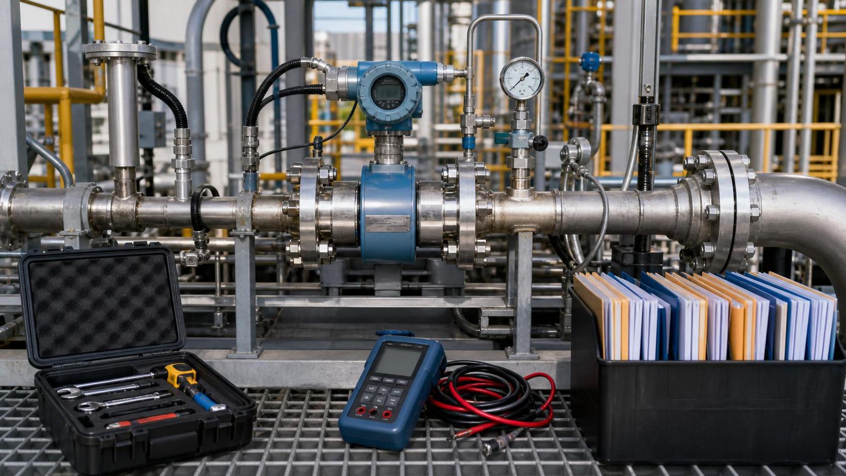
For flow measurement, for example, electromagnetic meters are often well suited to conductive liquids, but not hydrocarbons, deionized water with very low conductivity, or gas service. Coriolis meters offer direct mass flow and density information, yet their pressure drop, tube material, size range, and susceptibility to certain process vibrations must be reviewed. Differential-pressure flow remains widely applied and familiar, but impulse line design, plugging risk, density compensation, and permanent pressure loss can become decisive factors. Ultrasonic technologies may simplify retrofit work, though fluid cleanliness, acoustic path conditions, and mounting quality influence results.
Level measurement requires the same discipline. Radar is frequently chosen for challenging vessels because it is non-contact and can perform well under demanding pressure and temperature conditions. Still, false echoes from internals, low dielectric media, nozzle geometry, foam, and condensation need to be considered. Guided wave radar can provide a strong alternative in some applications, while hydrostatic measurement depends on stable density and correct reference-leg design. No single technology is universally “best.”
Process data should be gathered from operations, process engineering, maintenance, and site inspection—not copied only from a P&ID. Ask about cleaning cycles, batch transitions, abnormal viscosity, solids settling, flashing, vacuum service, line pulsation, and historical failure modes. Operators often know the conditions that do not appear in design documents.
Accuracy Is a System Property, Not a Transmitter Specification
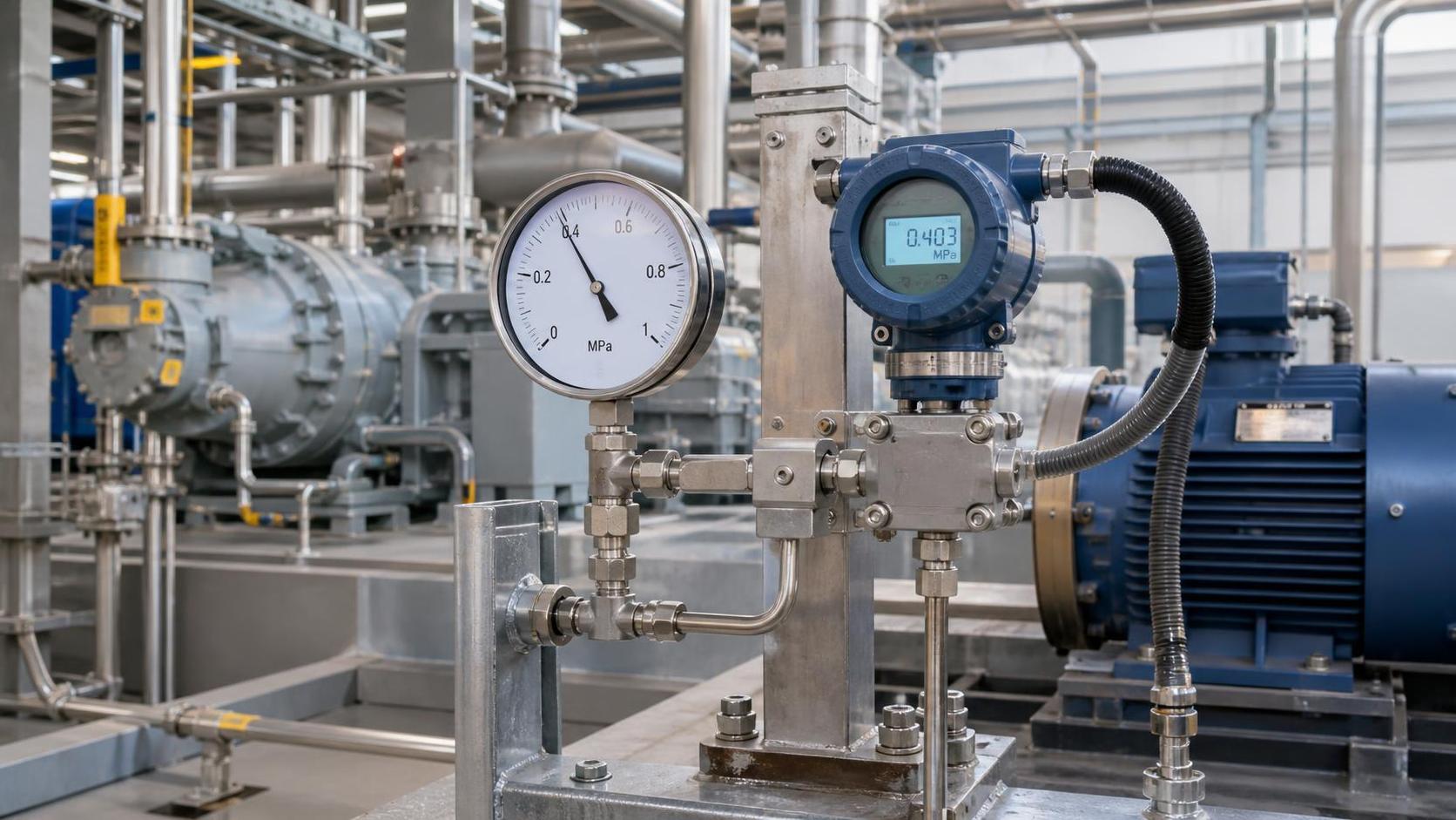
Accuracy claims can be misleading when they are evaluated in isolation. A pressure transmitter with excellent reference accuracy may still deliver a poor process value if the impulse lines are poorly routed, the process connection is plugged, the installed span is excessively wide, or ambient temperature shifts are ignored. Likewise, a highly accurate temperature sensor cannot correct for a thermowell placed in a stagnant zone or with excessive response lag.
Technical evaluation should therefore consider the complete measurement chain:
- Sensor and transmitter performance: reference accuracy, repeatability, stability, turndown, and ambient effects.
- Primary-element behavior: flow restriction, thermowell design, sensing location, nozzle arrangement, and process connection.
- Installation influence: grounding, shielding, straight-run requirements, vibration, orientation, impulse piping, and accessibility.
- Signal treatment: damping, filtering, scaling, compensation, and control-system resolution.
- Calibration uncertainty: test equipment capability, calibration interval, as-found results, and traceability requirements.
Range selection deserves special attention. Oversizing range “for safety” may reduce useful resolution around the normal operating point, while undersizing can cause saturation during transients. A better approach is to evaluate normal control range, startup conditions, credible upset limits, and any relief or trip thresholds separately. If one device cannot cover all conditions without a meaningful loss of performance, separate measurement paths may be justified.
Make Safety and Compliance Part of the Technical Specification
Safety requirements should be defined early, not appended after the preferred instrument has been selected. Hazardous-area classification, ignition protection method, enclosure rating, temperature class, material compatibility, and local electrical codes can sharply narrow the viable options. A device approved for one region or installation concept may not satisfy the requirements of another.
Review applicable approvals and documentation in relation to the actual project jurisdiction and site standard. Depending on the installation, this may include CE marking, UL or CSA listings, IECEx or ATEX documentation, ingress-protection ratings, and relevant ISO-based quality practices. The key is not to collect certificates indiscriminately; it is to verify that the delivered configuration, including cable entry, display, remote mount, and accessories, matches the certified arrangement.
Where an instrument contributes to functional safety, the review must go further. Check whether the device is suitable for the intended safety lifecycle, what failure-rate data and safety manuals are available, how diagnostics are treated, and what proof-test assumptions apply. A SIL-capable component does not automatically make a loop SIL compliant. Architecture, final element performance, common-cause failures, bypass management, testing intervals, and installation practices all matter.
Material selection also belongs in the safety conversation. Wetted parts must withstand corrosion, erosion, pressure, temperature, cleaning chemicals, and contamination risk. In oxygen service, food or pharmaceutical environments, sour service, chlorine handling, or abrasive slurries, a seemingly minor material mismatch can become an immediate reliability concern.
Evaluate Installation Before You Approve the Purchase
Many measurement problems are created before commissioning. The instrument may be correct on paper but impossible to install in accordance with its operating requirements. Technical evaluators should request dimensional drawings, installation guidance, connection details, and environmental limits while the layout is still flexible.
Consider the practical questions that affect uptime:
- Can the instrument be isolated, removed, and reinstalled without a lengthy shutdown?
- Is there sufficient clearance for covers, displays, local configuration tools, and cable bending radius?
- Will the mounting location expose electronics to radiant heat, flooding, heavy vibration, or corrosive atmosphere?
- Can technicians safely reach calibration points and drain, vent, or purge connections?
- Are process taps, impulse lines, capillaries, and seals designed to avoid plugging, freezing, gas pockets, or liquid legs?
- Does the selected technology require upstream and downstream straight pipe, stable flow profile, or a particular orientation?
A walkdown with process, mechanical, electrical, and maintenance representatives often reveals conflicts that a document review misses. This is especially valuable for brownfield upgrades, where legacy pipework, cable routes, confined spaces, and operating restrictions may shape the instrument choice more than the original process specification.
Choose Connectivity That Supports Operations, Not Just Integration
The familiar 4–20 mA signal remains valuable because it is simple, robust, and widely understood. However, modern facilities may also need digital diagnostics, remote parameterization, asset management, condition monitoring, or richer device status information. HART, FOUNDATION Fieldbus, Profibus PA, Modbus, Ethernet-based protocols, and wireless options each have a role, but their value depends on the site architecture and the team’s ability to use them.
Do not specify advanced communications merely because they are available. Ask which diagnostic alerts will be monitored, who will own them, how they will be prioritized, and whether the control or asset-management platform can interpret device-specific information. A diagnostic that is never configured, reviewed, or acted upon adds little resilience.
Cybersecurity and lifecycle compatibility deserve attention where instruments are networked. Confirm supported protocol versions, asset-management compatibility, firmware governance, access controls, and the process for managing updates. In long-lived industrial assets, an instrument is not only a sensor; it is part of an evolving operational technology environment.
Assess Reliability Through Maintenance Reality
Uptime is rarely protected by a low purchase price. It is protected by stable measurement, clear failure diagnostics, practical service access, available spares, and a maintenance strategy that fits the site’s capabilities. An instrument requiring specialist tools, frequent wet calibration, or difficult disassembly may carry a higher lifecycle burden than its initial cost suggests.
During evaluation, request more than a generic reliability statement. Review recommended calibration intervals, zero-check methods, sensor drift behavior, replaceable components, diagnostic coverage, environmental limitations, and repair pathways. Determine whether critical spare parts can be standardized across units and whether configuration data can be backed up and restored without ambiguity.
Maintenance history from comparable service is useful when it is specific enough to be meaningful. “Used successfully in industry” is not the same as demonstrated performance in a hot, vibrating, solids-laden, corrosive, or high-cycle application. The most relevant evidence comes from similar process media, operating ranges, installation arrangements, and duty cycles.
A Practical Evaluation Matrix for Technical Teams
A weighted evaluation matrix can bring discipline to a decision involving operations, engineering, procurement, and safety stakeholders. Avoid treating it as a bureaucratic scoring exercise. Its purpose is to make trade-offs visible and ensure that critical requirements cannot be obscured by a favorable unit price.
Typical categories include measurement suitability, installed accuracy, process and material compatibility, hazardous-area compliance, safety lifecycle support, installation complexity, diagnostic usefulness, integration compatibility, maintainability, supplier documentation, spare-parts strategy, and total cost of ownership. Weight the categories according to application criticality. For a noncritical utility loop, maintainability and standardization may carry substantial weight. For a protective pressure measurement on a hazardous process, failure behavior and safety evidence should dominate.
Require each score to be supported by evidence: a datasheet clause, approved drawing, test report, safety manual, material certificate, or documented installation assumption. This creates an audit trail that is valuable during design review, commissioning, incident investigation, and future replacement planning.
Common Selection Shortcuts That Create Long-Term Problems
Several shortcuts repeatedly weaken instrument decisions. One is selecting by nominal accuracy alone. Another is standardizing on a preferred vendor without checking whether the measurement principle fits the service. A third is assuming that a hazardous-area certificate resolves all safety questions. It does not address process compatibility, safety function design, or maintainability.
Technical teams also underestimate configuration management. Device tags, ranges, damping settings, alarm behavior, firmware revision, engineering units, and calibration records should be controlled from the start. A well-selected instrument can still become a source of confusion if field configuration differs from the approved design basis.
Finally, do not wait until commissioning to validate assumptions. Factory acceptance testing, configuration review, loop checks, and site acceptance testing should confirm the complete chain—from process connection and sensor orientation to control-system scaling, alarm action, and diagnostic visibility.
Selection Should End with a Defensible Operating Strategy
The right process control instrument is one that produces a trustworthy signal under the conditions the plant will actually face. It should be accurate enough for the decision, rugged enough for the environment, compliant with applicable requirements, understandable to the people who maintain it, and supportable throughout its service life.
For EPC teams, facility managers, and procurement directors, this means treating selection as a cross-functional engineering activity rather than a catalog exercise. A disciplined review of process conditions, measurement uncertainty, safety obligations, installation constraints, digital integration, and lifecycle support gives industrial instruments for process control their real value: fewer blind spots in operation, more confident decisions in the control room, and a stronger foundation for safe, available production.
Technical Specifications
- How to Select Electronic Hotel Key Card Locks for Guest Rooms and Staff AreasAuthor :Safety Compliance Lead
- How to Select Lab Instruments for Reliable Chemical Analysis WorkflowsAuthor :Precision Metrology Expert
- How to Size a UPS for Server Rooms: Load, Runtime, and Redundancy FactorsAuthor :Grid Infrastructure Analyst
Expert Insights

Chief Security Architect
Dr. Thorne specializes in the intersection of structural engineering and digital resilience. He has advised three G7 governments on industrial infrastructure security.
Related Analysis
- Sep 17, 2026How to Select Electronic Hotel Key Card Locks for Guest Rooms and Staff AreasAuthor :Safety Compliance Lead
- Sep 16, 2026How to Select Lab Instruments for Reliable Chemical Analysis WorkflowsAuthor :Precision Metrology Expert
- Sep 15, 2026How to Size a UPS for Server Rooms: Load, Runtime, and Redundancy FactorsAuthor :Grid Infrastructure Analyst
Core Sector // 01
Security & Safety
- What to Check When Sourcing Vibration Meters Wholesale for Industrial MaintenanceAuthor :Precision Metrology Expert

- How to Select Process Control Instruments for Accuracy, Safety, and UptimeAuthor :Precision Metrology Expert

- What Should Standards Compliance Analysis Training Cover Before an Audit?Author :Precision Metrology Expert

- Why Do Pressure Instruments Fail in High-Vibration Sites?Author :Precision Metrology Expert

- Is FM Software Integration Needed for Overseas Instrument Maintenance?Author :Precision Metrology Expert

- What Are the Differences Between Lab and Field Testing Equipment?Author :Precision Metrology Expert

- Is Independent Testing Necessary for Critical Safety Components?Author :Precision Metrology Expert

- How to Validate Industrial Application Scenarios Before ProcurementAuthor :Precision Metrology Expert