Choosing Contact Temperature Instruments: Accuracy, Range, and Response Time
Author
Date Published
Reading Time
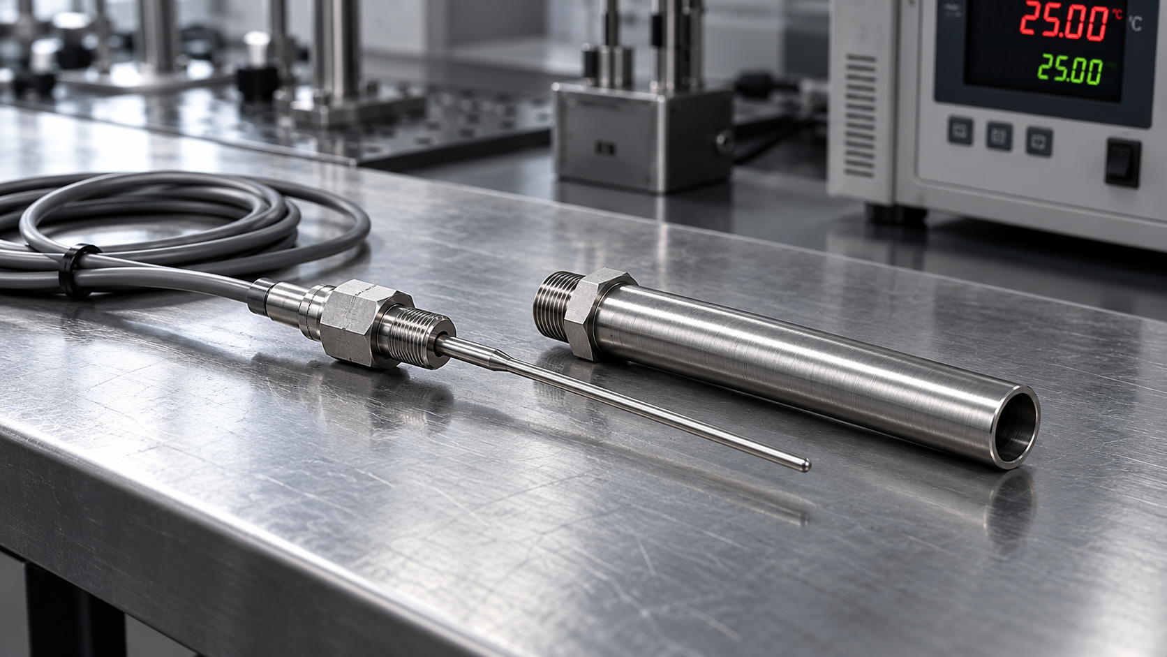
Select contact temperature measurement instruments by defining the allowable measurement error, the full temperature exposure, and the fastest process change that must be detected. An RTD is a strong starting point for stable, repeatable measurements within its assembly rating. A thermocouple suits higher temperatures and applications requiring a small, rugged sensing junction. A thermistor offers high sensitivity over a narrower operating window. The final choice depends on the installed probe, its electrical interface, and the heat transfer between the process and the sensing element.
A sensor with excellent calibration results can still report the wrong process temperature. Insufficient immersion, poor surface contact, protective hardware, and signal processing all affect the result. A defensible specification therefore assigns performance requirements to the complete measurement chain rather than relying on the sensing element’s tolerance alone.
Define the measurement before choosing the sensor
Start by identifying what temperature the measurement must represent: bulk liquid, flowing gas, a pipe surface, a bearing housing, or a small component. These are different thermal problems. A pipe surface measurement includes the effects of pipe material, wall thickness, insulation, and ambient heat loss; it does not automatically represent the fluid inside.
Separate the normal operating range from startup, cleaning, shutdown, and fault exposure. A probe that measures accurately during production may deteriorate during a hotter cleaning cycle. Cable insulation, seals, connectors, and transmitter electronics also need suitable ratings, even when the sensing element tolerates the exposure.
Define accuracy and speed in terms of the process decision. A slowly varying storage temperature places different demands on an instrument than a short heating cycle. Specify an allowable error at relevant operating points and a maximum acceptable delay for a defined temperature change. A single requirement such as “high accuracy and fast response” cannot support a meaningful comparison.
Where thermocouples, RTDs, and thermistors differ
Sensor family alone does not establish response time. A small thermistor suspended in moving fluid can respond quickly, while the same element inside a thick protective housing responds slowly. A thermocouple mounted in a heavy thermowell can lag behind a compact RTD installed directly in the process.
Within each family, construction matters. Thin-film and wire-wound RTDs have different mechanical and thermal characteristics; the better option depends on the actual assembly and service conditions. Thermocouple alloys also differ in temperature capability and compatibility with the surrounding atmosphere. Comparing generic labels without these details leaves major performance differences unresolved.
Interpret accuracy as a measurement-chain requirement
A datasheet accuracy statement may describe the sensing element, the electronic input, or the complete instrument under reference conditions. Establish which components are included and whether the specification applies across the required temperature and ambient ranges. A calibration certificate documents behavior at the tested points; it does not remove installation effects or guarantee future stability.
Build the error assessment around the actual chain: sensor, leads, connections, transmitter or readout, and installation. Distinguish fixed bias from repeatability and drift. A stable offset may be corrected through calibration, while changing immersion conditions or intermittent electrical noise require changes to the installation or wiring.
For RTDs, two-wire connections include lead resistance in the measured resistance. Three-wire compensation relies on sufficiently matched lead resistances and a compatible input circuit. Four-wire measurement largely removes lead-resistance effects at the sensing connection, making it useful when cable resistance would consume too much of the error allowance.
Thermocouples require a compatible input and cold-junction compensation. The instrument must account for the temperature at the transition from thermocouple conductors to its terminals. Temperature gradients across that terminal area create errors that a probe-only calibration will not reveal. Incorrect extension wire, reversed polarity, or unsuitable connections introduce additional problems.
RTDs and thermistors require excitation, which generates heat in the sensing element. Self-heating becomes more significant when heat dissipates poorly, such as in still air or weak surface contact. Reducing excitation helps only if the readout still achieves adequate signal quality. Evaluate this effect under the intended measurement conditions.
When combining uncertainty contributions, use a method appropriate to their relationships. Independent random contributions and correlated systematic effects require different treatment. Simply adding every datasheet limit, or automatically combining every value statistically, can produce a misleading result.
Response time belongs to the installed assembly
A response-time value is incomplete without its test conditions. Moving water, still air, and contact with a metal surface provide very different heat-transfer rates. Meaningful comparisons require the same medium, flow condition, temperature step, immersion, and response criterion.
For an approximately first-order response, the time constant describes the time needed to register about 63% of a temperature step. A specification expressed as time to 90% represents a later point in the response. These values cannot be compared directly without understanding the response model, and a real probe assembly can exhibit more than one thermal time constant.
Sheath diameter, wall thickness, internal insulation, tip geometry, and protective fittings influence thermal lag. Smaller probes generally reduce thermal mass, but they also change mechanical strength and durability. A grounded thermocouple junction often transfers heat faster than an otherwise comparable ungrounded construction, while electrical connection to the sheath can complicate grounding and noise control.
A thermowell adds another thermal path. Its wall, tip thickness, internal clearance, and contact with the probe influence response. A well-fitted, spring-loaded insert can improve contact at the tip, but it cannot eliminate the thermowell’s thermal mass. In flowing service, reducing thermowell dimensions also requires mechanical assessment because flow-induced vibration and loading constrain the design.
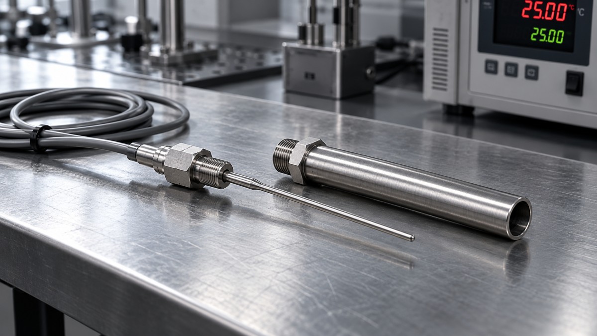
Include transmitter damping, input filtering, scan intervals, and control-system processing in the response requirement. A fast sensing junction followed by heavy digital filtering still produces a delayed indication. Filtering suppresses noise, but it cannot recover a temperature event that the probe never followed.
Installation can dominate the error budget
An immersion probe exchanges heat with both the process and its surroundings. If too much heat travels along the stem toward a cooler fitting or ambient air, the sensing element settles below the local process temperature. The reverse occurs when the surrounding structure is hotter than the process.
There is no universal insertion depth that resolves every installation. Required immersion depends on probe geometry, stem conductivity, process heat transfer, and the temperature difference to the surroundings. Where access permits, compare readings at progressively greater insertion depths under stable conditions. A reading that continues to shift indicates that immersion or spatial temperature variation remains significant.
Surface measurement introduces a different balance. Contact pressure, surface curvature, coatings, oxidation, and the mounting method affect thermal resistance between the surface and sensor. Insulation over the sensing area reduces ambient influence, although it can also alter the local surface temperature. Attachment methods must therefore be evaluated as part of the measurement.
A surface probe and an immersed probe can disagree while both function correctly: they may be measuring different temperatures. Before attributing the difference to calibration, establish whether a real gradient exists through the pipe wall, across a vessel, or along the flow path.
Match temperature range to materials and electrical conditions
The usable range of an assembly is limited by its least tolerant component. A high-temperature sensing element does not establish an equivalent rating for the sheath, cable transition, connector, or seal. Ask for continuous-service and short-exposure limits separately, including any conditions attached to those ratings.
Process chemistry changes material suitability. Corrosion, oxidation, contamination, and permeation can damage a sheath or change sensor behavior before an obvious mechanical failure appears. Specify the process medium and relevant cleaning chemicals alongside temperature and pressure. Selecting a familiar sheath material without considering the actual exposure leaves this failure mechanism unresolved.
Mechanical conditions also influence the choice. Vibration, bending, repeated thermal cycling, and cable movement stress different parts of the assembly. A probe that survives a static temperature test has not demonstrated suitability for a vibrating machine or a rapidly cycling process.
Electrical isolation deserves explicit attention where the process equipment and readout can sit at different ground potentials. An ungrounded junction or isolated transmitter can address particular electrical paths, with consequences for response, installation, and fault detection. Specify the required arrangement rather than assuming every metal-sheathed probe behaves alike.
Make performance claims comparable before approval
A useful evaluation package describes the exact probe construction and its measurement conditions. Request the sensing element type, wiring arrangement, sheath material and diameter, active sensing location, insertion geometry, and compatible input configuration. Accuracy statements should identify their temperature range, ambient conditions, and included components.
Resolve the remaining performance questions through focused evidence:
- Calibration evidence: points covering the working region, stated uncertainty, and identification of whether the probe alone or the assembled measurement chain was calibrated.
- Response data should name the test medium, flow condition, mounting arrangement, and response criterion. An unexplained “fast response” claim provides no comparison basis.
- Stability after exposure: where cycling or sustained heat matters, request relevant drift data and the conditions behind it. Initial tolerance does not describe service-life behavior.
For a stable liquid process requiring close temperature control, begin with an RTD assembly and assess wiring, immersion, and calibration uncertainty. For a hotter process or one needing a very small junction, evaluate a compatible thermocouple construction and its drift and compensation requirements. For a compact assembly operating within a narrow temperature window, assess a thermistor with its matched resistance curve and readout.
When installation effects remain uncertain, a trial using the intended mounting, protection hardware, cable route, and signal settings provides the most relevant evidence. Acceptance should depend on measurement error and response under those conditions. Record that configuration with the approved specification so that replacement assemblies preserve the behavior that was actually evaluated.
Technical Specifications
- Choosing Contact Temperature Instruments: Accuracy, Range, and Response TimeAuthor :Precision Metrology Expert
- Nucor Raises Hot-Rolled Coil Spot Price by $15 to $1,270 per Short TonAuthor :
- Choosing an Industrial Electrical Infrastructure Supplier: Compliance and Lead TimesAuthor :Grid Infrastructure Analyst
Expert Insights

Chief Security Architect
Dr. Thorne specializes in the intersection of structural engineering and digital resilience. He has advised three G7 governments on industrial infrastructure security.
Related Analysis
- Oct 28, 2026Choosing Contact Temperature Instruments: Accuracy, Range, and Response TimeAuthor :Precision Metrology Expert
- Oct 27, 2026Nucor Raises Hot-Rolled Coil Spot Price by $15 to $1,270 per Short TonAuthor :
- Oct 27, 2026Choosing an Industrial Electrical Infrastructure Supplier: Compliance and Lead TimesAuthor :Grid Infrastructure Analyst
Core Sector // 01
Security & Safety
- Choosing Contact Temperature Instruments: Accuracy, Range, and Response TimeAuthor :Precision Metrology Expert

- How to Verify ATEX Pressure Transmitters for Overseas Oil and Gas SitesAuthor :Precision Metrology Expert

- Does Global Industrial Core Provide Better Test Equipment Compliance Data Than Generic Industrial Hubs?Author :Precision Metrology Expert

- Is Global Industrial Core Reliable for Overseas EPC Test Equipment?Author :Precision Metrology Expert

- Choosing a Bluetooth Total Station: Software Compatibility and Connection RangeAuthor :Precision Metrology Expert

- Material Testing Standards: ASTM E8 vs. ISO 6892-1 for Metal Tensile TestsAuthor :Precision Metrology Expert

- How to Verify Accuracy in Industrial Measurement Data and Test ReportsAuthor :Precision Metrology Expert

- Selecting a Steam Vortex Flow Meter: Sizing, Pressure, and Temperature LimitsAuthor :Precision Metrology Expert