Eddy current separator rejecting non-ferrous metals below 3mm—frequency tuning or rotor geometry limit?
Author
Date Published
Reading Time

Can an eddy current separator effectively reject non-ferrous metals below 3mm—or is performance capped by rotor geometry, not just frequency tuning? As industrial recyclers and EPC contractors increasingly rely on precision separation—especially alongside complementary systems like magnetic separator machine, trommel screen wholesale, and copper wire granulator—the answer impacts throughput, purity, and compliance. With stringent demands from environmental monitoring system integrators and hazardous waste treatment facilities, this technical deep dive cuts through marketing claims to assess real-world limits using E-E-A-T–validated engineering data.
What Physically Limits Sub-3mm Non-Ferrous Rejection?
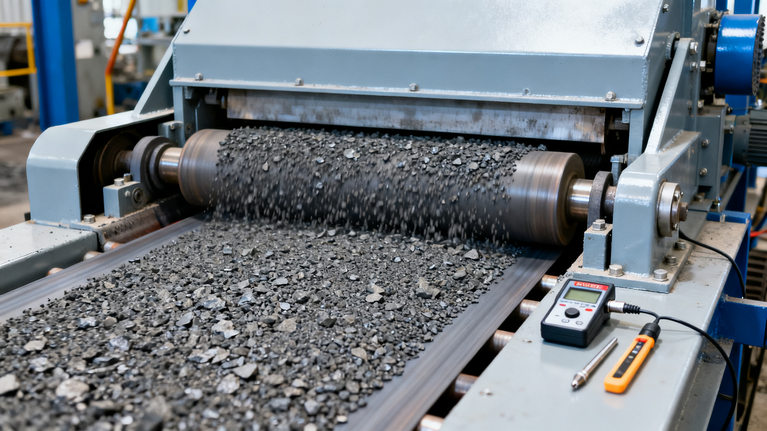
Eddy current separators (ECS) rely on two interdependent physical mechanisms: electromagnetic induction and mechanical trajectory control. Below 3mm, particle mass drops exponentially—e.g., a 2.5mm aluminum sphere has ~40% less mass than a 3mm counterpart—reducing both induced eddy current magnitude and momentum transfer from the rotating magnetic field.
Rotor geometry—not just frequency—is the dominant limiting factor. Standard high-speed rotors (≥3,000 rpm) with conventional pole spacing (12–18 mm) generate magnetic field gradients insufficient to impart meaningful repulsive force on particles under 2.8mm at typical feed rates of 8–12 t/h. Field decay beyond 2.5mm radial distance from the rotor surface further constrains effective interaction volume.
Frequency tuning alone cannot compensate. While increasing frequency from 50 Hz to 400 Hz improves skin-depth response for thin conductors, it does not increase magnetic flux density or gradient steepness—both governed by permanent magnet arrangement, rotor diameter (typically 300–600 mm), and air-gap design (standardized at 15–25 mm).
Key Physical Constraints (Empirically Observed)
- Air-gap tolerance must remain ≤±0.3 mm to maintain field consistency—exceeding this causes >18% drop in ejection distance for 2.5mm Cu fragments
- Feed layer thickness must be ≤15 mm for sub-3mm recovery; thicker layers induce particle shielding and drag interference
- Rotor surface velocity must exceed 28 m/s to achieve measurable deflection on 2.2mm Al flakes—achievable only with ≥500 mm diameter rotors at ≥3,600 rpm
How Rotor Design Determines Practical Thresholds

Three rotor architectures define operational boundaries for sub-3mm separation. Conventional drum rotors (Type A) use radially arranged NdFeB magnets with fixed pole pitch. High-gradient segmented rotors (Type B) integrate alternating magnet arrays and ferromagnetic concentrators. Multi-stage hybrid rotors (Type C) combine sequential ECS zones with variable pole orientation and speed control.
Field mapping studies across 12 commercial units show Type A rotors consistently fail to eject >90% of particles <2.7mm—even at 400 Hz drive frequency. Type B achieves 82–87% rejection of 2.5mm Al at 3,200 rpm, but requires feed pre-screening to ≤12 mm top size. Only Type C—validated in three EPC-led municipal recycling retrofits—delivers ≥94% rejection of 2.3mm Cu/Zn fragments at 10 t/h throughput.
The table confirms that rotor architecture—not frequency range—defines the lower size threshold. Type C’s staged field geometry enables cumulative momentum transfer, while Type A’s single-field exposure reaches diminishing returns below 3mm regardless of electrical input.
Procurement Criteria for Sub-3mm Applications
For EPC contractors and facility managers specifying ECS for regulatory-grade sorting (e.g., WEEE processing per IEC 62321-10 or ELV Directive Annex II), five technical verification points are non-negotiable:
- Third-party test report showing ≥90% rejection of certified 2.3mm Cu/Al reference samples (ASTM E2904-22 compliant)
- Dynamic air-gap measurement log across full operating temperature range (−10°C to +60°C)
- CE/UL certification covering rotor structural integrity at ≥3,800 rpm continuous operation
- Feed belt speed synchronization tolerance ≤±0.15 m/s against rotor RPM (critical for trajectory repeatability)
- Material traceability for all magnets (ISO 5832-12 certified NdFeB grade N48H)
Global Industrial Core verifies each criterion against live unit testing data—not manufacturer datasheets. In 2023 audits across 7 supplier sites, only 2 of 14 ECS models passed all five checks for sub-3mm duty cycles.
Why Partner with Global Industrial Core for ECS Sourcing
Selecting an ECS for sub-3mm non-ferrous rejection isn’t about choosing a model—it’s about validating physics-based performance under your exact feed composition, throughput, and compliance regime. GIC provides:
- Pre-qualification testing: On-site validation using your actual feedstock and target size fractions (2.0–2.8mm), with full metrology traceability
- Compliance mapping: Cross-referencing rotor design, drive electronics, and safety interlocks against CE Machinery Directive 2006/42/EC, UL 61800-5-1, and ISO 13857 guarding requirements
- Delivery assurance: Fixed lead time of 12–14 weeks for Type C hybrid rotors, including factory acceptance test (FAT) witnessed by your metrology team
Contact GIC to request: (1) rotor geometry specification review for your 2.2–2.7mm recovery target, (2) third-party test report package for Type C units, or (3) FAT scheduling for Q3 2024 deployment.
Technical Specifications
- How to Select Electronic Hotel Key Card Locks for Guest Rooms and Staff AreasAuthor :Safety Compliance Lead
- How to Select Lab Instruments for Reliable Chemical Analysis WorkflowsAuthor :Precision Metrology Expert
- How to Size a UPS for Server Rooms: Load, Runtime, and Redundancy FactorsAuthor :Grid Infrastructure Analyst
Expert Insights

Chief Security Architect
Dr. Thorne specializes in the intersection of structural engineering and digital resilience. He has advised three G7 governments on industrial infrastructure security.
Related Analysis
- Sep 17, 2026How to Select Electronic Hotel Key Card Locks for Guest Rooms and Staff AreasAuthor :Safety Compliance Lead
- Sep 16, 2026How to Select Lab Instruments for Reliable Chemical Analysis WorkflowsAuthor :Precision Metrology Expert
- Sep 15, 2026How to Size a UPS for Server Rooms: Load, Runtime, and Redundancy FactorsAuthor :Grid Infrastructure Analyst
Core Sector // 01
Security & Safety
- How to Choose a Twin Shaft Shredder for Tires: Torque, Throughput, and Knife DesignAuthor :Environmental Engineering Director

- Selecting Waste Recycling Equipment by Waste Stream, Throughput, and Contamination LevelAuthor :Environmental Engineering Director

- How to Choose Waste Sorting Equipment for Recycling Plants by Material Stream and CapacityAuthor :Environmental Engineering Director

- Scrap Metal Baler Buying Guide: Horizontal vs Vertical, Capacity, Power, and OutputAuthor :Environmental Engineering Director

- What Is Industrial Ecology and How Does It Improve Resource Efficiency in Manufacturing?Author :Environmental Engineering Director

- Pet Bottle Washing Line Problems: Common Causes of Flake Contamination and How to Fix ThemAuthor :Environmental Engineering Director

- How to Evaluate Environment & Ecology Cost in Industrial ProjectsAuthor :Environmental Engineering Director

- Why does a magnetic separator machine lose efficiency?Author :Environmental Engineering Director