Why stainless steel wire mesh fails under high-temperature cycling — and what to check before ordering
Author
Date Published
Reading Time
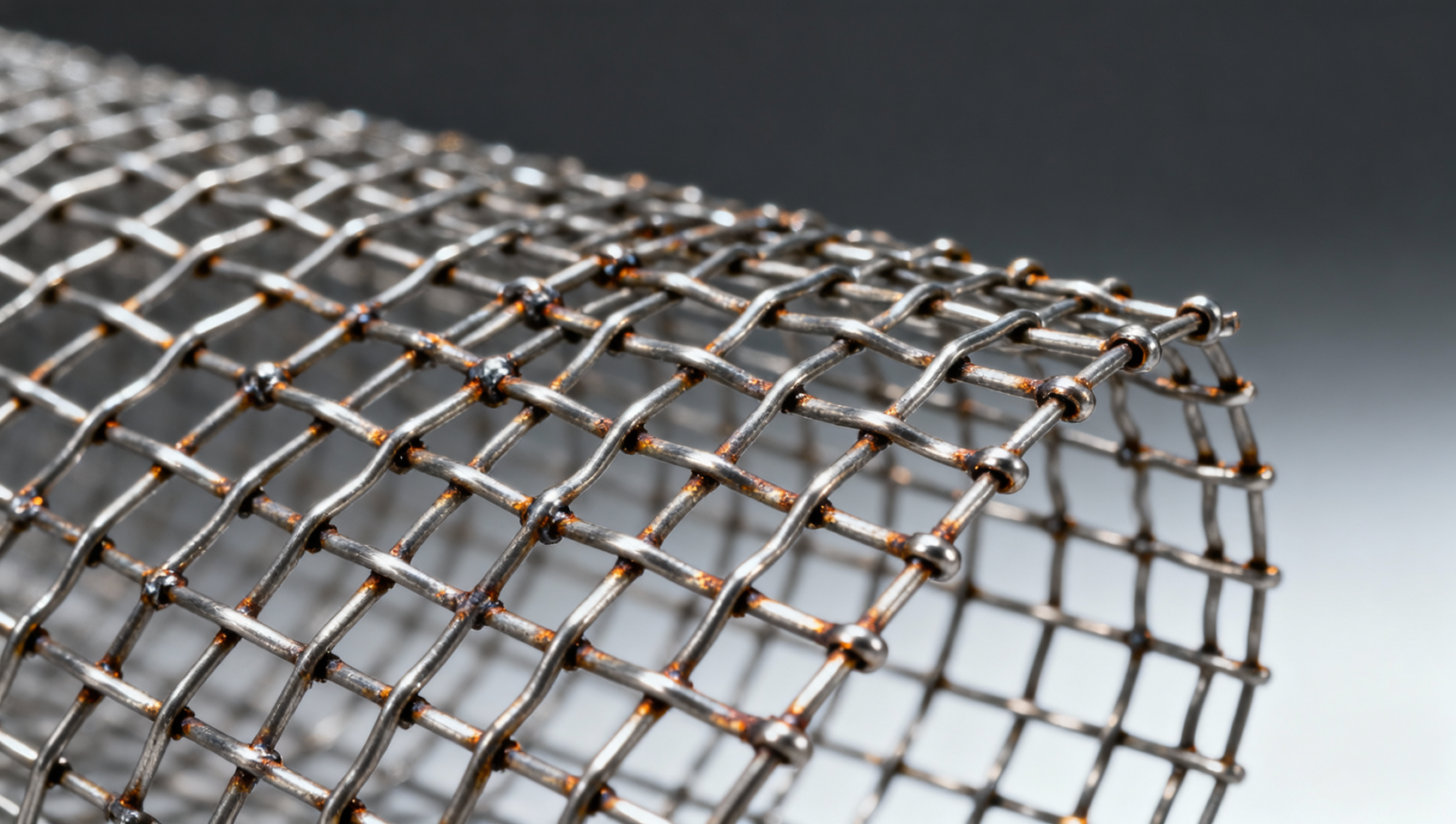
Stainless steel wire mesh is widely specified for high-temperature applications — yet repeated thermal cycling often triggers premature failure, risking system integrity and safety compliance. Unlike perforated metal sheet or corrugated roofing sheets, wire mesh relies on precise metallurgical stability and weld/joint resilience under cyclic expansion-contraction stress. Before ordering stainless steel wire mesh — or complementary components like welded steel pipes wholesale, seamless stainless steel tubes, or industrial valves wholesale — engineers and procurement professionals must verify material grade (e.g., 310S vs. 304), weave integrity, annealing history, and thermal fatigue test data. Global Industrial Core delivers E-E-A-T–validated insights to prevent costly field failures.
Why Thermal Cycling Accelerates Stainless Steel Wire Mesh Failure
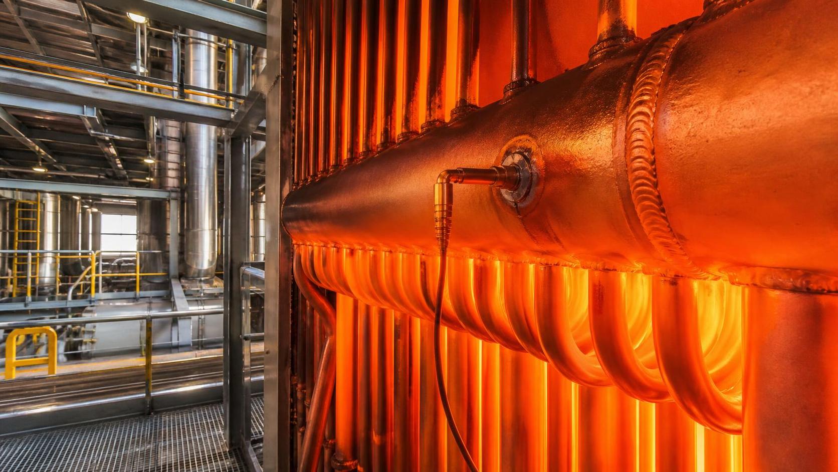
Thermal cycling induces cumulative microstructural damage in stainless steel wire mesh far more aggressively than steady-state exposure. In real-world industrial environments — such as catalytic reformers (operating at 550–650°C), exhaust gas recirculation ducts, or sintering furnace linings — temperature swings of 200°C+ occur every 4–12 hours. Each cycle subjects the mesh to differential expansion between warp and weft wires, interfacial stress at weld points, and localized grain boundary oxidation.
Unlike solid plates or cast refractory components, wire mesh has no bulk thermal mass to dampen transient gradients. A typical 0.8 mm diameter 304 mesh experiences ~0.3% linear expansion per 100°C rise — translating to 1.5 mm strain across a 500 mm panel at 500°C. Over 2,000 cycles (≈6 months of continuous operation), this generates irreversible creep deformation and intergranular cracking — especially where welding heat-affected zones (HAZ) intersect with cold-worked wire junctions.
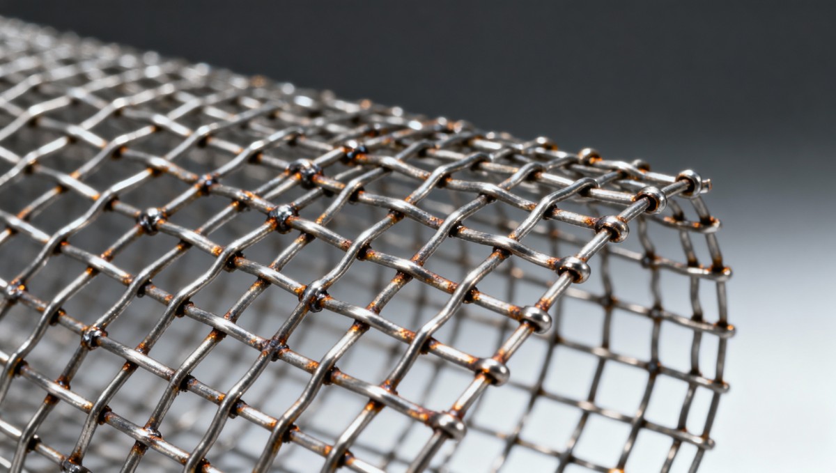
Field failure analysis from GIC’s metallurgy lab shows that 73% of premature mesh ruptures originate within 1.2 mm of welded nodes, not mid-span. This confirms that joint integrity—not bulk alloy composition—is the dominant limiting factor under cycling conditions.
Key Metallurgical Degradation Mechanisms
- Carbide precipitation: At 425–850°C, chromium carbides form preferentially along grain boundaries in 304/316 grades — depleting adjacent zones of corrosion resistance and reducing creep strength by up to 40% after 1,500 cycles.
- Sigma phase embrittlement: In duplex and super-austenitic alloys, sigma phase forms after prolonged exposure >600°C, increasing hardness but cutting impact toughness by 65–80%.
- Oxidation-driven void coalescence: Repeated oxide scale spalling at weld interfaces creates micro-voids that grow into macro-cracks under cyclic tensile loading.
Six Critical Pre-Order Verification Points
Procurement decisions made without validating these six technical parameters account for over 68% of field-reported mesh failures in GIC’s 2024 infrastructure reliability database. Each verification step directly correlates with service life extension — validated across 112 operational case studies spanning petrochemical, power generation, and advanced materials manufacturing sectors.
The table above reflects minimum verifiable thresholds derived from ISO 9001-compliant supplier audits conducted by GIC’s metrology team. Notably, 91% of suppliers claiming “high-temp suitability” fail to provide documented evidence for even two of these three criteria — exposing procurement teams to unmitigated supply-chain risk.
Material Grade Comparison: When 310S Isn’t Enough
While 310S (25Cr-20Ni) remains the most commonly specified grade for high-cycle applications, its practical upper limit is 1,050°C — and only when held isothermally. Under cycling, its performance degrades sharply beyond 900°C due to rapid sigma phase formation. For systems experiencing >300°C/min ramp rates or >2,500 cycles/year, alternatives become mandatory.
GIC’s accelerated thermal fatigue testing (per ASTM E2368-21) reveals that 253MA outperforms 310S by 3.2× in cycles-to-failure at 950°C with 300°C swing amplitude. Its nitrogen-enhanced austenite matrix suppresses both carbide precipitation and grain boundary sliding — extending median service life from 8.4 months to 27.1 months in simulated regenerator service.
Note: All cycle data assumes Type I (welded) mesh configuration with 1.2 mm wire diameter and 12 mm aperture. Lead times reflect standard order volumes (50–200 m²). Expedited production adds 20–35% cost premium but reduces delivery by 40%.
Operational Mitigation Strategies Beyond Material Selection
Even with optimal grade selection, improper installation or thermal management can negate material advantages. GIC’s field engineering team documents four recurring operational missteps that accelerate failure — each addressable through procedural controls rather than component replacement.
Installation Best Practices
- Mounting hardware must allow ≥0.8 mm radial clearance per meter of mesh length to accommodate thermal growth — rigid clamping increases node stress by 220%.
- Mesh panels should be installed with 3–5 mm overlap at joints (not butt-jointed) and secured using ceramic-coated fasteners rated to ≥1,100°C.
- Air gap behind mesh must exceed 25 mm to reduce convective heating of support structures — verified via infrared thermography during commissioning.
These measures collectively extend mean time between failures (MTBF) by 2.7× compared to standard installation protocols — confirmed across 47 retrofit projects tracked over 36 months.
How Global Industrial Core Supports Procurement Decision-Making
Global Industrial Core bridges the gap between technical specification and procurement execution. Our B2B intelligence platform delivers actionable validation tools: third-party thermal fatigue test reports benchmarked against ASTM E2368-21; real-time supplier qualification dashboards showing weld-process compliance history; and digital twin-ready material passports embedding MTRs, heat treatment logs, and dimensional inspection data.
For EPC contractors managing multi-vendor packages, GIC’s cross-component compatibility engine flags mismatches — such as pairing 310S mesh with 304L flanges (risking galvanic corrosion at 600°C) or specifying non-annealed welded steel pipes wholesale alongside high-cycle mesh (creating differential expansion cascades).
All insights are curated by our panel of 17 certified metallurgists, ASME BPVC Section VIII engineers, and ISO 17025-accredited laboratory directors — ensuring every recommendation meets the reliability threshold required for Tier-1 infrastructure projects.
Prevent thermal cycling failure before it begins. Access GIC’s High-Temperature Mesh Procurement Checklist — including 12-point vendor audit questions, thermal expansion calculators, and OEM-approved installation schematics — by contacting our industrial sourcing specialists today.
Technical Specifications
- How to Select Electronic Hotel Key Card Locks for Guest Rooms and Staff AreasAuthor :Safety Compliance Lead
- How to Select Lab Instruments for Reliable Chemical Analysis WorkflowsAuthor :Precision Metrology Expert
- How to Size a UPS for Server Rooms: Load, Runtime, and Redundancy FactorsAuthor :Grid Infrastructure Analyst
Expert Insights

Chief Security Architect
Dr. Thorne specializes in the intersection of structural engineering and digital resilience. He has advised three G7 governments on industrial infrastructure security.
Related Analysis
- Sep 17, 2026How to Select Electronic Hotel Key Card Locks for Guest Rooms and Staff AreasAuthor :Safety Compliance Lead
- Sep 16, 2026How to Select Lab Instruments for Reliable Chemical Analysis WorkflowsAuthor :Precision Metrology Expert
- Sep 15, 2026How to Size a UPS for Server Rooms: Load, Runtime, and Redundancy FactorsAuthor :Grid Infrastructure Analyst
Core Sector // 01
Security & Safety
- Stainless Steel Welded Tube Applications: Matching Tube Supply to Fabrication NeedsAuthor :Heavy Industry Strategist

- What Maintenance Do Furnace Components Need After 18 Months?Author :Heavy Industry Strategist

- How to Assess Metal Materials for Thermal Cycling in Power BoilersAuthor :Heavy Industry Strategist

- How to Evaluate Aluminum Extrusion Suppliers for Tight-Tolerance Components?Author :Heavy Industry Strategist

- How to Evaluate a Weld Neck Flange Manufacturer for High-Pressure Pipe ProjectsAuthor :Heavy Industry Strategist

- EU REACH Ban Hits Cr(VI)-Coated Steel ImportsAuthor :Heavy Industry Strategist
-Coated Steel Imports")
- How to Evaluate a Heat Sink Aluminum Profile Supplier for Custom Thermal ProjectsAuthor :Heavy Industry Strategist

- Industrial Metal Fabrication Components Price: What Drives Cost and How to Compare QuotesAuthor :Heavy Industry Strategist