Why Do Pressure Instruments Fail in High-Vibration Sites?
Author
Date Published
Reading Time

A pressure gauge that reads steadily on the workshop bench can begin drifting, sticking, leaking, or failing completely soon after it is installed on a vibrating pump skid, compressor package, pipeline rack, or offshore utility module. The first reaction is often to blame the instrument. In practice, the gauge may only be the visible casualty of a larger installation problem.
This becomes especially frustrating when replacement instruments fail in the same location. Maintenance teams may replace the gauge, tighten the connection, and return the equipment to service, only to find a cracked case, broken pointer movement, loose terminal, or unstable signal at the next inspection. In high-consequence operations, unreliable pressure indication can delay troubleshooting, create uncertainty during startup, and lead to unnecessary shutdown decisions.
The question, Why do pressure instruments fail after installation in high-vibration overseas sites?, usually has more than one answer. Mechanical vibration, pressure pulsation, unsupported tubing, unsuitable mounting, temperature exposure, moisture ingress, and transport-related damage can overlap. Finding the real cause requires looking at the instrument, the process connection, the mounting arrangement, and the surrounding equipment as one system.
The failure often starts before the instrument is switched on
High-vibration sites are not limited to obviously violent rotating machinery. A gauge mounted near a reciprocating compressor may experience continuous high-amplitude movement, but a transmitter on a long pipe run can also be affected by resonance, fluid hammer, valve cycling, or vibration transmitted through a steel support. The instrument may appear secure while its internal parts are being subjected to thousands of small stress cycles.
Conventional analog pressure gauges contain delicate mechanical components: a Bourdon tube, linkage, sector gear, pinion, pointer, and bearing points. Repeated vibration can wear or loosen these parts. Typical symptoms include a pointer that oscillates excessively, fails to return to zero, reads differently depending on orientation, or settles at an inconsistent value.
Electronic pressure transmitters are not immune. Their sensing cells may tolerate vibration well within their design limits, yet problems can develop in electrical terminals, cable entries, connectors, display modules, mounting brackets, or impulse tubing. A transmitter can also produce a noisy output because the process pressure itself is pulsating, even if the electronics are intact.
The practical lesson is simple: a pressure instrument should not be selected only by pressure range, connection size, and output type. The actual installation environment matters just as much.

Separate vibration damage from pressure pulsation
These two issues are often confused because both can make an indicator move erratically. They require different corrections.
Mechanical vibration is physical movement transmitted from equipment, pipework, structures, or supports into the instrument. A gauge case may visibly shake, mounting hardware may loosen, and fatigue cracks may appear at threaded connections, welds, capillary lines, or unsupported tubing. The pointer can blur while the real process pressure remains relatively stable.
Pressure pulsation is a rapid change in the pressure being measured. It is common downstream of reciprocating pumps, compressors, diaphragm pumps, piston systems, and fast-switching valves. In this situation, the gauge pointer is responding to real pressure fluctuations. A transmitter may show a rapidly varying output that is mistaken for electrical interference.
Both conditions can occur at the same time. For example, a gauge mounted directly on a compressor discharge line may receive pulsating pressure through the process connection and mechanical vibration through the piping. Replacing it with the same dry gauge is unlikely to change the outcome.
Signs that point toward the root cause
The failure pattern usually provides useful clues. A cracked lens or damaged case suggests external impact, excessive vibration, improper installation torque, or an incompatible environment. A pointer that shakes but remains accurate when the equipment is idle suggests vibration or pulsation during operation. A gauge that reads high or low permanently after a short period may have suffered overpressure, fatigue, corrosion, or internal mechanical wear.
If instruments repeatedly leak at the threaded process connection, inspect more than the thread sealant. Excessive cantilever loading from a heavy gauge, rigid piping misalignment, vibration at the connection, or an inadequate support bracket can place stress on the fitting. A small leak can become worse as the connection moves through repeated vibration cycles.
For electronic instruments, intermittent readings frequently point to cable or terminal problems. Look for loose conductor terminations, damaged shielding, poor gland selection, unsupported cable weight, moisture inside an enclosure, or connector movement caused by vibration. Do not assume every unstable signal is a failed sensor.
Another overlooked sign is the timing of the failure. If the instrument works during commissioning but becomes unreliable after equipment reaches full load, investigate machine speed, pressure surges, thermal expansion, and vibration transmission under operating conditions. Inspection during a shutdown alone may not reveal the source.
Mounting choices make a major difference
Direct mounting is convenient, but it is not always appropriate. A pressure gauge attached directly to a vibrating line becomes part of that vibrating assembly. If the gauge is heavy relative to the connection, the bending load at the root can be significant. The same concern applies to electronic transmitters with display housings, valve manifolds, and cable connections.
Where process conditions allow, remote mounting can reduce mechanical stress. This may involve locating the instrument on a rigid, independently supported bracket and connecting it through suitable tubing or a capillary arrangement. The bracket must be designed as part of the solution. A thin sheet-metal plate, a long unsupported arm, or a bracket fixed to the same vibrating machine frame may amplify movement rather than reduce it.
A sound mounting arrangement is short, rigid where rigidity is needed, and supported at practical intervals. It avoids placing instrument weight on small-bore tubing. It also allows access for reading, calibration, drainage, venting, and safe replacement. In corrosive or wet locations, the support material and fasteners need environmental consideration; a strong bracket that rapidly corrodes is not a long-term vibration solution.
For gauges exposed to moderate vibration, liquid-filled cases can help damp pointer movement and reduce wear in the movement mechanism. However, filling is not a universal cure. The fill fluid must suit the temperature range and application, and excessive vibration can still damage the instrument, connection, or mounting hardware. A filled gauge mounted on a failing bracket remains a poorly supported gauge.
Impulse lines and tubing deserve the same attention as the instrument
In many installations, the pressure instrument is remote from the process takeoff point. The impulse line then becomes part of the measurement system. Poor routing can introduce vibration, blockage, trapped gas or liquid, heat transfer, and response delays.
Long, unsupported small-bore tubing is especially vulnerable. It can vibrate like a spring, fatigue near compression fittings, and transmit movement directly into the transmitter connection. Tubing should be routed with controlled bends, secure supports, and enough allowance for thermal movement without leaving a long free span. Supports should restrain damaging movement without crushing the tube or creating sharp stress points.
The line must also match the service. Gas service generally needs a route that avoids liquid accumulation; liquid service should avoid trapped gas pockets. Steam applications require suitable arrangements to protect the sensing element from excessive temperature and maintain a stable pressure reference. For dirty, viscous, crystallizing, or solid-laden media, a narrow impulse path may plug long before the instrument itself develops a fault.
When pressure pulsation is the main problem, a snubber, restrictor, pulsation dampener, or another application-appropriate device may be considered. Selection should be deliberate. Too much restriction can make the reading slow to respond and may hide meaningful process changes. Too little restriction may offer no effective damping. The goal is not simply a calmer pointer; it is a reliable measurement that still responds appropriately to the process.
Instrument selection needs to reflect the actual duty
Pressure range selection is a basic starting point. An instrument that operates continuously near the upper end of its range may be more exposed to fatigue and overpressure damage than one selected with reasonable allowance for normal operation and credible transients. At the same time, choosing an excessively wide range can reduce useful resolution and make small changes difficult to interpret.
Material compatibility matters at the wetted connection and sensing element. Corrosive process media, salt-laden air, chemical washdown, and humid outdoor conditions can attack connections and housings. A compatible process material does not automatically mean the external case, fasteners, cable gland, and mounting accessories are suitable for the site.
Temperature also changes the decision. High process temperature can affect accuracy, fill fluid behavior, seals, electronics, and the lifespan of internal components. Low ambient temperatures may increase the viscosity of gauge fill fluid or affect elastomer seals. Direct exposure to sunlight can heat an enclosure far beyond the expected ambient air temperature.
For electronic instruments, verify the required output, power supply, environmental enclosure, electrical connection method, and any site-specific hazardous-area requirements before installation. These checks should be based on the project specification and applicable local requirements, not assumptions carried over from a different site.
A practical investigation sequence after repeat failures
When an instrument has failed more than once, avoid immediately ordering a higher-priced replacement. Start by preserving evidence. Photograph the installed condition before removal, including the bracket, tubing route, cable support, process connection, and nearby machinery. Note whether the failure occurred during startup, steady operation, cycling, or after a maintenance event.
Then remove the instrument safely under the site’s isolation and depressurization procedures. Inspect for external clues: loose fasteners, cracked fittings, rub marks, corrosion, water ingress, damaged threads, bent tubing, and signs of overpressure. If it is a gauge, check whether the pointer returns to zero after pressure is removed. If it is a transmitter, inspect terminals, connector pins, gland seals, and cable strain relief before declaring the sensing element defective.
Next, compare the actual location with the installation drawing and instrument documentation. Has a support been omitted? Has the instrument been moved closer to a machine? Has a temporary line become permanent? Are there process changes, new valve cycles, changed pump speeds, or different operating pressures? Many repeat failures follow a modification that was not considered during the original selection.
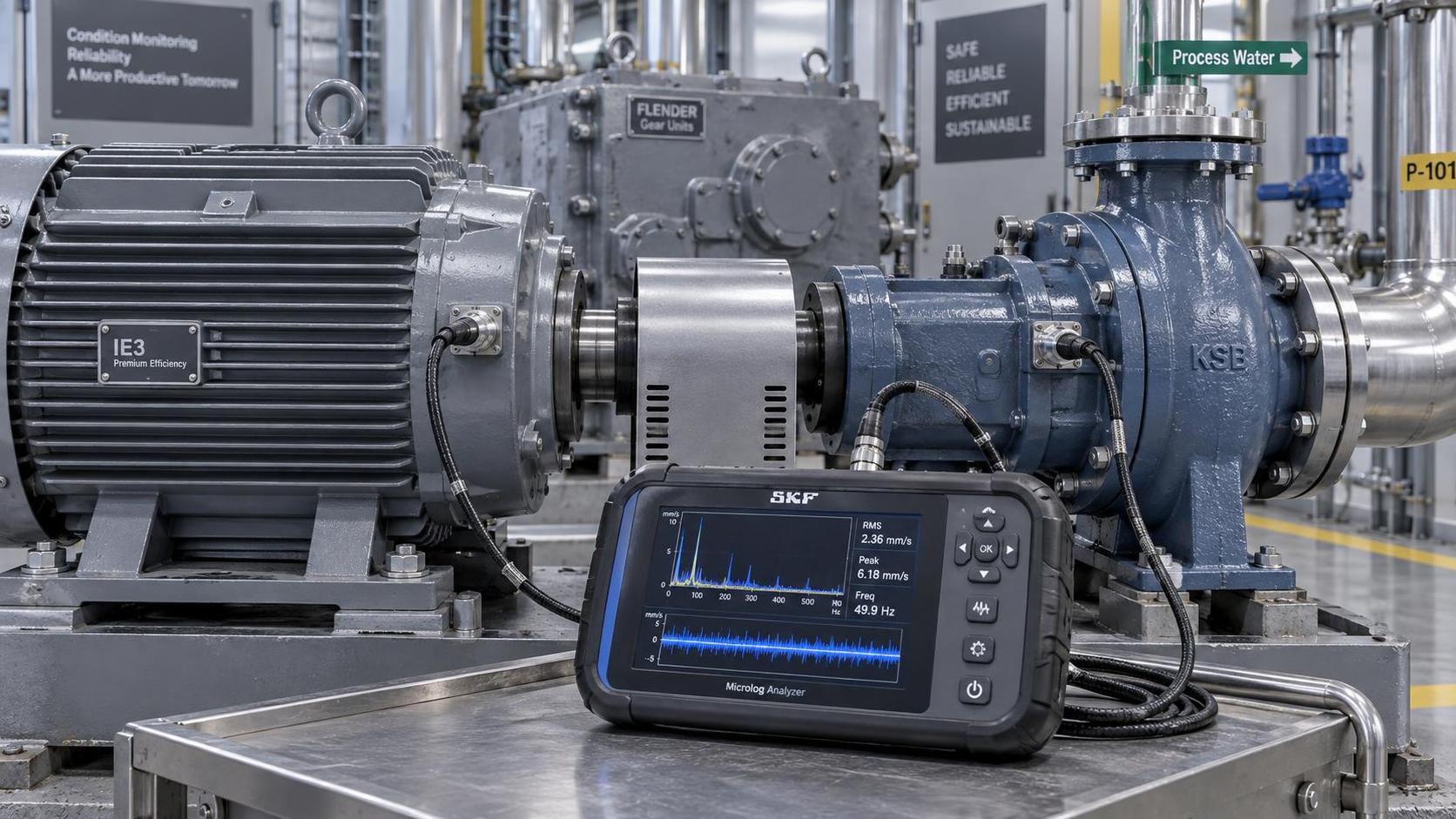
Where available, vibration measurement and process trending can help distinguish structural vibration from pressure pulsation. The purpose is not to collect data for its own sake. It is to identify whether the remedy should focus on relocation, bracket redesign, damping, tubing support, process pulsation control, or a different instrument configuration.
Common shortcuts that create recurring problems
One shortcut is adding more thread sealant to a connection that is moving under load. Sealant may temporarily mask leakage, but it does not correct bending stress or vibration fatigue. Another is installing a needle valve and assuming it will solve pulsation. A valve can provide restriction, but its suitability depends on the service, setting, cleanliness, and required response time.
It is also risky to tighten mounting hardware repeatedly without checking the support structure. Over-tightening can damage threads, distort brackets, or make later inspection difficult. The better approach is to confirm that the instrument is properly supported and that the mounting arrangement is not transferring unnecessary stress into the process connection.
Finally, do not treat a liquid-filled gauge as a substitute for diagnosis. It can be useful when selected correctly, but it cannot compensate for severe pipe vibration, damaging pressure spikes, incompatible media, or an unsupported installation.
Questions raised during site troubleshooting
Can a pressure gauge fail even if the process pressure is within range?
Yes. The pressure range may be suitable while vibration, pulsation, corrosion, temperature, mounting stress, or repeated pressure cycling damages the gauge. A range check is necessary, but it is only one part of the assessment.
Is a remote-mounted gauge always better in a vibrating location?
Not always. Remote mounting can reduce direct vibration exposure, but the connecting tubing and bracket must be properly designed and supported. Poorly routed tubing or a flexible bracket can introduce new failure modes.
Should every vibrating application use a filled gauge?
No. Filled gauges are often considered where pointer damping is needed, but the fill type, ambient temperature, process conditions, mounting arrangement, and required readability must all be suitable. In some duties, a different measurement arrangement is more appropriate.
When should a specialist review the installation?
Seek qualified engineering support when failures recur, when the pressure point is tied to safety-critical operation, when hazardous or high-temperature media are involved, or when changes to piping, supports, pulsation control, or instrument selection are being considered. Replacing instruments without resolving the installation cause can turn a manageable problem into a recurring maintenance burden.
Technical Specifications
- How to Select Electronic Hotel Key Card Locks for Guest Rooms and Staff AreasAuthor :Safety Compliance Lead
- How to Select Lab Instruments for Reliable Chemical Analysis WorkflowsAuthor :Precision Metrology Expert
- How to Size a UPS for Server Rooms: Load, Runtime, and Redundancy FactorsAuthor :Grid Infrastructure Analyst
Expert Insights

Chief Security Architect
Dr. Thorne specializes in the intersection of structural engineering and digital resilience. He has advised three G7 governments on industrial infrastructure security.
Related Analysis
- Sep 17, 2026How to Select Electronic Hotel Key Card Locks for Guest Rooms and Staff AreasAuthor :Safety Compliance Lead
- Sep 16, 2026How to Select Lab Instruments for Reliable Chemical Analysis WorkflowsAuthor :Precision Metrology Expert
- Sep 15, 2026How to Size a UPS for Server Rooms: Load, Runtime, and Redundancy FactorsAuthor :Grid Infrastructure Analyst
Core Sector // 01
Security & Safety
- What to Check When Sourcing Vibration Meters Wholesale for Industrial MaintenanceAuthor :Precision Metrology Expert

- How to Select Process Control Instruments for Accuracy, Safety, and UptimeAuthor :Precision Metrology Expert

- What Should Standards Compliance Analysis Training Cover Before an Audit?Author :Precision Metrology Expert

- Why Do Pressure Instruments Fail in High-Vibration Sites?Author :Precision Metrology Expert

- Is FM Software Integration Needed for Overseas Instrument Maintenance?Author :Precision Metrology Expert

- What Are the Differences Between Lab and Field Testing Equipment?Author :Precision Metrology Expert

- Is Independent Testing Necessary for Critical Safety Components?Author :Precision Metrology Expert

- How to Validate Industrial Application Scenarios Before ProcurementAuthor :Precision Metrology Expert