How Ductile Iron Pipe Joints Affect Installation Reliability and Leak Control
Author
Date Published
Reading Time
Joint Design Is a System Decision, Not a Fitting Detail
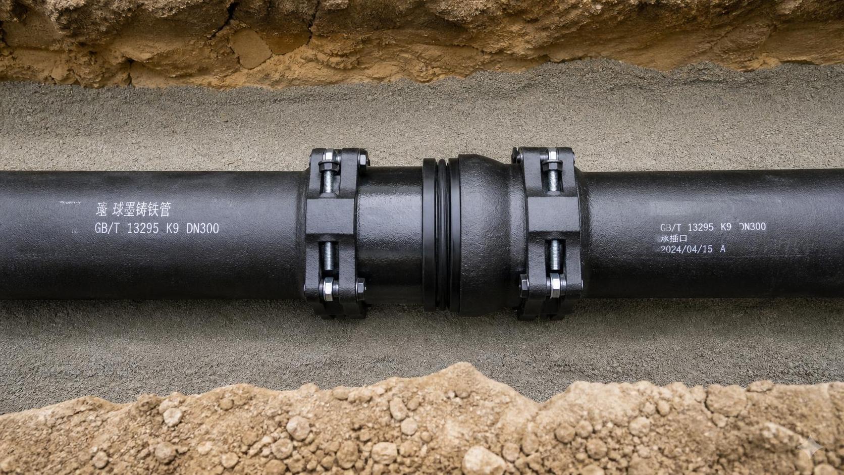
A buried pipeline can have sound pipe barrels and still develop leakage, movement, or early maintenance problems at its joints. For project managers, this changes how installation reliability should be evaluated. The joint is where pipe geometry, gasket condition, trench preparation, thrust restraint, installation workmanship, and pressure testing meet. A weakness in any one of those areas can undermine the expected performance of the line.
Ductile iron systems are often selected for buried water, wastewater, industrial utility, and pressure conveyance duties because the pipe body is mechanically robust. Yet the reliability of a completed main depends heavily on whether the selected joint can accommodate the route, pressure conditions, soil behavior, and construction method. A flexible push-on joint may suit long, relatively straight buried runs. A restrained joint may be necessary where pressure thrust, steep grades, shallow cover, or limited space makes external thrust blocks impractical. Flanged connections can be useful around valves, chambers, and equipment, but demand stricter alignment and bolting control.
The practical question is not simply whether the pipe and joint are compatible. It is whether the assembled connection will remain sealed and stable after bedding is placed, the trench is backfilled, pressure cycles begin, and the surrounding ground experiences seasonal or operational movement.
What Makes a Ductile Iron Joint Seal
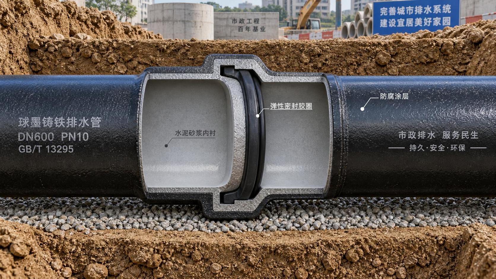
Most gasketed buried-pipe joints rely on controlled compression of an elastomeric gasket between the spigot end of one pipe and the bell or socket of the next. During assembly, the spigot enters the bell and moves past the gasket. The gasket is then compressed into its seating area, forming a pressure-responsive seal. Internal line pressure generally helps energize the gasket against the mating surfaces, provided the gasket was correctly seated and the joint remains within its designed deflection and insertion limits.
This mechanism is forgiving of small angular changes along a route, but it is not immune to poor installation. A gasket that is twisted, contaminated, damaged by a sharp edge, or displaced from its groove may not produce a continuous sealing surface. Excessive insertion force can also signal a misaligned pipe, incorrect lubrication, an obstructed bell, or a gasket problem that should be corrected rather than forced through.
Pipe material, wall class or pressure rating, internal lining, external coating, and joint configuration need to be reviewed as one package. A project team assessing available ductile iron pipe options should confirm that the bell-and-spigot dimensions, gasket system, coating condition, and intended joint type align with the project specification rather than treating the pipe barrel as the sole procurement item.
Why pipe class and joint selection must be coordinated
Pipe class is commonly tied to the anticipated internal pressure, external loading, installation depth, handling conditions, and applicable project requirements. It does not automatically determine the suitability of every joint detail. A line may require a heavier wall section at a road crossing because of soil and traffic loads, while needing restrained joints at bends or vertical changes because hydraulic thrust must be controlled. These are separate design questions that must meet at the final bill of materials.
Coatings and linings matter as well. External protection is intended to reduce corrosion exposure in the installed environment, while internal linings are selected with the conveyed fluid and operational conditions in mind. Damaged coating around a joint, an unprotected cut end, or an incompatible repair method can create a localized durability concern even where the rest of the pipeline is properly protected. Inspection should include the pipe ends, bells, spigots, and areas affected by lifting, storage, cutting, and assembly.
How Joint Type Changes Construction Risk
Joint selection affects more than leakage risk. It influences crew sequence, excavation length, required equipment, allowable alignment tolerance, the need for thrust restraint, and how readily a section can be dismantled or modified. The table below outlines the broad decision logic commonly used during planning. Actual selection should follow the pipeline design, manufacturer instructions, and the governing project specification.
A flexible joint should not be used as a substitute for proper route geometry. Repeatedly taking the maximum permitted deflection at every joint can create cumulative alignment errors and impose uneven stress on the seals. If a route needs a meaningful change of direction, a purpose-designed bend or fitting is usually the more controlled solution. Similarly, restrained joints do not eliminate the need to verify pipe support and soil interaction. They change the way longitudinal load is transmitted through the line.
Leak Paths Often Begin Before the Hydrostatic Test
Many joint leaks are introduced during handling and assembly, then revealed only during testing or early operation. The most common causes are simple, but their consequences can be difficult to isolate once a trench is backfilled.
- Contaminated joint surfaces: Soil, gravel, dried coating debris, or packing material in the bell groove can prevent the gasket from seating evenly.
- Incorrect gasket placement: A gasket installed in the wrong orientation, left twisted, or stretched unevenly may seal initially but become vulnerable under pressure or movement.
- Damaged spigot end: Chips, deep scratches, burrs, or an out-of-round end can compromise the contact surface or damage the gasket during insertion.
- Improper lubrication: The specified lubricant helps the spigot pass the gasket without rolling or tearing it. Unapproved products may affect rubber compatibility or fail to provide predictable assembly behavior.
- Over-insertion or under-insertion: Witness marks or insertion references help crews verify that the spigot has reached the intended position while preserving the joint’s movement allowance.
- Unsupported fittings: Valves, branches, bends, and transitions can impose concentrated loads. If these are not supported and restrained as designed, joint displacement may follow.
- Poor bedding and backfill: Point loads, voids beneath the barrel, oversized rock, or uneven compaction can distort alignment and concentrate stress near joints.
For project managers, the important lesson is that pressure testing is a verification stage, not the primary quality-control process. A test may identify a leak, but it rarely explains whether the root cause was material damage, a trapped gasket, excessive deflection, poor thrust control, or a local trench condition. Installation records and hold-point inspections make diagnosis far more efficient.
Thrust, Movement, and the Difference Between Sealing and Restraint
A gasketed joint can be watertight without being designed to resist longitudinal separation. Internal pressure creates thrust at changes in direction, changes in diameter, branches, valves, and closed ends. If that thrust is not resisted by designed thrust blocks, restrained joints, or another engineered method, a joint can pull apart even when its gasket and pipe surfaces were initially in good condition.
This distinction is especially relevant on constrained sites. A concrete thrust block requires suitable bearing against stable undisturbed soil and must be placed so that it does not interfere with later access or damage adjacent pipe protection. Where excavations are narrow, soils are uncertain, fittings are close together, or concrete curing would disrupt the schedule, a restrained system may be evaluated. The restraint design must account for pressure, fitting geometry, soil conditions, cover depth, and the length of pipe needed to develop resistance. Selecting restrained fittings at isolated points without checking the required restrained run can leave the system incomplete.
Ground movement creates a related but different concern. Settlement, expansive soils, poor compaction, vibration, and thermal movement in exposed sections can alter joint alignment. Limited joint deflection can help accommodate normal route changes and minor movement, but it should not be assumed to compensate for substantial settlement or inadequate foundation conditions. In problematic ground, the pipe support concept and backfill specification deserve the same attention as the joint schedule.
Inspection Points That Belong in the Installation Plan
A workable inspection plan separates receiving checks, pre-assembly checks, assembly controls, and test-stage verification. This prevents a crew from discovering a correctable issue after the pipeline has been covered.
Receiving and storage
- Confirm pipe, fittings, gaskets, and restraint components against the approved submittal or purchase schedule.
- Inspect bells and spigots for cracks, deformation, coating damage, contamination, and impact damage from transport.
- Keep gaskets clean, protected from direct sunlight where practicable, and away from oils, solvents, or sharp objects.
- Store pipe on stable supports to reduce rolling, localized damage, and contamination of joint ends.
Before each joint is made
- Clean the bell interior, gasket recess, gasket, and spigot end.
- Check that the gasket is the correct type and size for the joint system.
- Examine the spigot end for burrs or damage that could cut or displace the gasket.
- Confirm line, grade, bedding support, and the planned direction of assembly before insertion.
- Use approved lubrication and apply it only where the installation procedure calls for it.
During assembly and backfill
- Use insertion marks to verify joint position and avoid unintended over-insertion.
- Measure or visually control deflection so that individual joints remain within the permitted range.
- Install restraint components in the required orientation and sequence; do not assume they are interchangeable across systems.
- Place initial backfill carefully around the pipe haunches and joint area, avoiding rock or hard debris that can create point loading.
- Record repaired coatings, cut lengths, unusual assembly resistance, and any joints reopened for correction.
Testing Should Confirm Both Tightness and Construction Discipline
Hydrostatic or other specified pressure testing is normally performed after sufficient installation and temporary restraint measures are in place. The exact test method, pressure, duration, permissible makeup water, and acceptance criteria are project-specific. Teams should avoid treating a single test outcome as a blanket assurance of long-term integrity. Air removal, temperature variation, temporary plugs, test-section boundaries, and test equipment can all affect interpretation.
If a leak occurs, excavating only the visibly wet location may not be enough. The investigation should check whether the pipe was fully inserted, whether the gasket remained seated, whether the joint was deflected beyond its allowable range, whether the fitting was adequately restrained, and whether a local bedding defect has altered alignment. Repeating a test without correcting the initiating condition can merely delay the same failure.
FAQ
Can a push-on joint control pressure thrust at a bend?
Not by itself in most applications. A push-on joint is primarily a sealing connection. Bends and other thrust locations usually require a designed restraint method, such as thrust blocking, restrained joints, or another engineered arrangement.
Does a higher pipe class eliminate joint leakage risk?
No. A heavier or differently rated pipe barrel may address pressure or external load requirements, but leakage remains dependent on gasket condition, joint cleanliness, correct assembly, allowable deflection, and stable support.
Should a joint be disassembled if insertion resistance is unusually high?
Usually, the cause should be investigated rather than forcing completion. Common issues include an improperly seated gasket, insufficient or incorrect lubricant, misalignment, debris in the bell, or damage at the spigot end.
Are restrained joints always preferable?
They are appropriate where the design requires axial load transfer. Using them everywhere may add cost and installation complexity without addressing the actual risk. The route, pressure, fittings, soil conditions, and restraint design should determine their use.
A Practical Procurement and Technical Review Checklist
Before release for manufacture or delivery, project teams can reduce field uncertainty by confirming the following:
- Pipe diameter, wall class or pressure designation, length schedule, and fitting requirements are consistent across drawings and purchase documents.
- Each pipeline segment identifies the intended joint type, including restrained locations, flange interfaces, and transition connections.
- Gasket material is suitable for the conveyed medium and operating environment specified for the project.
- Internal lining and external coating requirements include treatment of cuts, repairs, fittings, and joint-end handling.
- Manufacturer installation instructions are available to the construction team before field assembly begins.
- Thrust-control details identify the responsibility for design verification, material supply, and field inspection.
- Testing procedures define section limits, filling and air-release steps, acceptance criteria, and documentation requirements.
- Inspection hold points are scheduled before joint concealment, initial backfill, and pressure testing.
Reliable pipeline installation comes from matching the joint to the forces it must manage, then protecting the details that make the seal work. When pipe selection, trench conditions, restraint design, and inspection controls are coordinated early, leakage becomes a managed construction risk rather than an expensive surprise after commissioning.
Technical Specifications
- How to Select Electronic Hotel Key Card Locks for Guest Rooms and Staff AreasAuthor :Safety Compliance Lead
- How to Select Lab Instruments for Reliable Chemical Analysis WorkflowsAuthor :Precision Metrology Expert
- How to Size a UPS for Server Rooms: Load, Runtime, and Redundancy FactorsAuthor :Grid Infrastructure Analyst
Expert Insights

Chief Security Architect
Dr. Thorne specializes in the intersection of structural engineering and digital resilience. He has advised three G7 governments on industrial infrastructure security.
Related Analysis
- Sep 17, 2026How to Select Electronic Hotel Key Card Locks for Guest Rooms and Staff AreasAuthor :Safety Compliance Lead
- Sep 16, 2026How to Select Lab Instruments for Reliable Chemical Analysis WorkflowsAuthor :Precision Metrology Expert
- Sep 15, 2026How to Size a UPS for Server Rooms: Load, Runtime, and Redundancy FactorsAuthor :Grid Infrastructure Analyst
Core Sector // 01
Security & Safety
- How to Size a Wafer Butterfly Valve for HVAC Chilled-Water and Heating LoopsAuthor :Environmental Engineering Director

- How Pressure Class and Joint Design Affect Long-Term Performance of Ductile Iron Pipes in Drainage InfrastructureAuthor :Environmental Engineering Director

- How Ductile Iron Pipe Joints Affect Installation Reliability and Leak ControlAuthor :Environmental Engineering Director

- How to Size Effluent Treatment Equipment for Variable Industrial Wastewater LoadsAuthor :Environmental Engineering Director

- US Battery Push Raises New Entry Rules for SuppliersAuthor :Environmental Engineering Director

- EU EMC Rule Tightens for Water Treatment ExportsAuthor :Environmental Engineering Director

- EU REACH Restriction Targets PFAS Water Treatment ImportsAuthor :Environmental Engineering Director

- EU Mandates EN 14113:2026 for Water Treatment ExportsAuthor :Environmental Engineering Director