Industrial Water Treatment
How Pressure Class and Joint Design Affect Long-Term Performance of Ductile Iron Pipes in Drainage Infrastructure
Discover how ductile iron pipe pressure class and joint design directly impact drainage system longevity—engineer for performance, not just compliance.
Author
Environmental Engineering Director
Date Published
Sep 11, 2026
Reading Time
Pressure Class and Joint Design: Core Determinants of Service Life in Drainage Applications
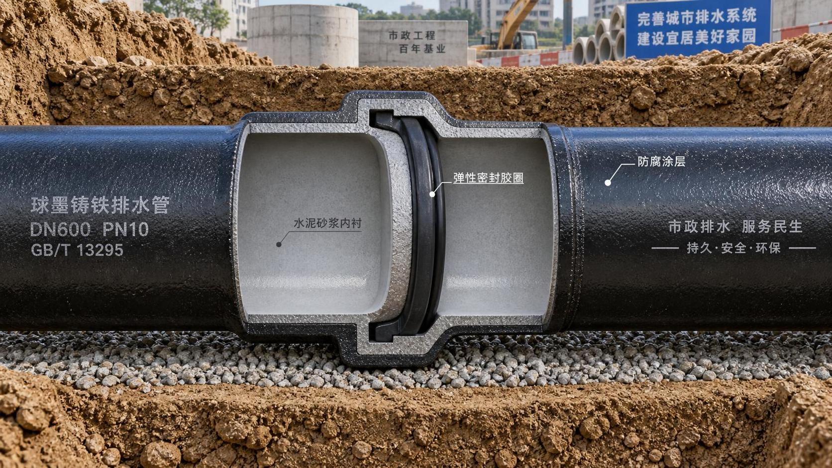
Ductile iron pipe has long been specified for gravity-fed and low-pressure drainage infrastructure—particularly where durability, corrosion resistance, and structural integrity are non-negotiable. Yet technical evaluations often focus narrowly on material grade or coating systems, overlooking two interdependent variables that govern long-term field performance: pressure class selection and joint design configuration. These are not interchangeable specifications. They represent distinct engineering decisions—one tied to internal and external load management, the other to deformation tolerance, sealing reliability, and installation margin.
In drainage contexts, “pressure class” does not refer to operating pressure alone. It reflects the pipe’s capacity to withstand combined loads: soil cover, traffic surcharge, groundwater buoyancy, and transient events like trench backfill compaction or localized ground settlement. A Class 150 ductile iron pipe (per ISO 2531 or EN 545) is rated for 15 bar hydrostatic test pressure—but its real-world suitability depends on burial depth, bedding quality, and whether the system operates under full flow or partial fill. Over-specifying pressure class adds unnecessary weight and cost; under-specifying risks ovalization, joint separation, or accelerated fatigue at support points.
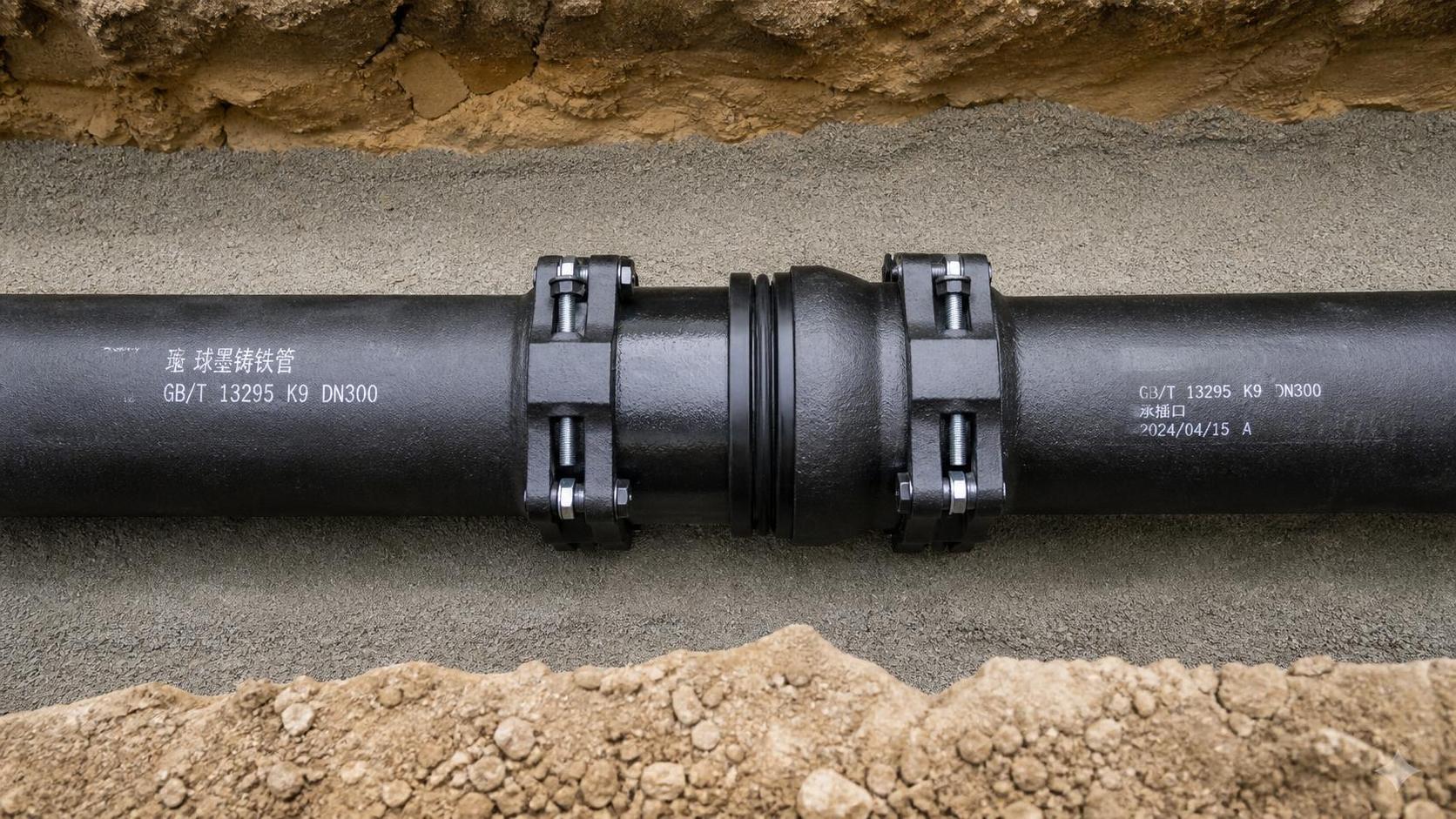
Joint design plays an equally decisive role—especially where differential settlement or thermal cycling is expected. Push-on, mechanical, and restrained joints each respond differently to axial movement, angular deflection, and hydrostatic thrust. In unconfined trench conditions common in municipal drainage upgrades, a non-restrained push-on joint may perform reliably at shallow depths with stable soils. But in reclaimed land, high-water-table zones, or near roadways with heavy axle loads, even minor joint displacement can compromise seal integrity over time—leading to infiltration, exfiltration, or sediment ingress that degrades hydraulic efficiency and increases maintenance frequency.
How Application Context Shapes Selection Criteria
Drainage infrastructure spans heterogeneous environments—from rural stormwater conduits buried under 1 m of topsoil to urban combined sewers installed beneath active arterial roads. The functional requirements—and failure modes—differ accordingly.
| Application Scenario | Typical Burial Depth | Key Load Considerations | Recommended Pressure Class Range (ISO 2531) | Preferred Joint Type | Rationale |
|----------------------|------------------------|--------------------------|----------------------------------------------|------------------------|-----------|
| Rural stormwater outfall | 1–2 m | Low traffic, stable subgrade | K7/K8 (≈ Class 100–125) | Push-on with elastomeric gasket | Sufficient for gravity flow; lower stiffness reduces risk of cracking during light backfill |
| Urban combined sewer (under sidewalk) | 2–4 m | Moderate live load, variable bedding | K9/K10 (≈ Class 150) | Restrained push-on or mechanical joint | Controls axial movement under cyclic loading; accommodates minor angular deviation during installation |
| Highway underdrain (beneath pavement base) | 3–6 m | High dynamic axle loads, compaction risk | K10/K12 (≈ Class 150–200) | Fully restrained mechanical joint | Prevents joint pull-out during vibratory compaction; maintains alignment under repeated flexure |
| Industrial site drainage (chemical exposure) | 1–3 m | Corrosive soils, possible thermal gradients | K9 minimum | Double-gasketed mechanical joint | Dual sealing barrier against aggressive leachates; isolates pipe body from soil contact |
This table reflects typical practice—not prescriptive rules. Actual selection requires local geotechnical input, hydraulic modeling (e.g., peak flow velocity, surcharge duration), and verification of bedding support modulus. For example, a K9 pipe installed on granular bedding with E’ ≥ 5 MPa behaves differently than the same pipe on poorly compacted clay with E’ < 1 MPa—even at identical depth.
Technical Evaluation Checklist for Procurement Teams
When reviewing tenders or supplier submittals for drainage projects, technical evaluators should verify the following—not as standalone items, but as an integrated set:
- **Pressure class justification**: Does the submission reference actual design loads (e.g., AASHTO LRFD or Eurocode 7 calculations), or rely solely on catalog defaults? Is the selected class matched to verified bedding class and trench width?
- **Joint behavior data**: Are angular deflection limits, axial pull-out resistance, and hydrostatic test pressures provided per joint type—not just per pipe? Do test reports reflect real-world conditions (e.g., gasket compression under soil load, not just water pressure)?
- **Coating compatibility**: Does the external protection system (cement-mortar lining, polyethylene encasement, or zinc–polymer composite) remain effective at joint interfaces after deflection? Some coatings crack or delaminate at high angular strain.
- **Installation tolerance allowances**: What maximum allowable misalignment (angular or axial) is permitted per joint? How does this align with contractor capability and survey control precision on site?
- **Third-party verification**: Are joint performance claims backed by independent testing to EN 598 (for sewer applications) or ISO 16135 (for restrained joints)? Manufacturer declarations alone are insufficient for critical infrastructure.
These points shift evaluation from compliance checking to performance assurance. A ductile iron pipe meeting EN 545 does not automatically ensure long-term drainage integrity—unless its pressure class and joint system are validated for the specific load path and deformation envelope of the installation.
Frequently Asked Questions
Q: Can a higher pressure class ductile iron pipe compensate for poor bedding or inadequate trench support?
No. Increased wall thickness improves resistance to collapse but does not eliminate ovalization under uneven support. Excessive stiffness may even amplify stress concentration at unsupported spans. Proper bedding and haunching remain primary load-distribution mechanisms.Q: Are restrained joints always necessary in drainage applications?
Not universally. In stable, shallow, gravity-only systems with minimal expected settlement, properly installed push-on joints demonstrate decades of reliable service. Restraint becomes critical where axial forces exceed gasket friction resistance—or where joint leakage could trigger erosion or undermine adjacent structures.Q: How do temperature fluctuations affect joint performance in above-ground or shallow-buried drainage runs?
Thermal expansion in ductile iron is modest (~10.8 µm/m·°C), but cumulative movement across multiple joints can generate measurable axial thrust. Mechanical joints with integral restraint better accommodate this than push-on types relying solely on gasket compression.Q: Does internal lining thickness impact pressure class rating?
No. Cement-mortar or epoxy linings serve hydraulic and corrosion functions only. Pressure class is determined by the structural wall thickness and tensile strength of the ductile iron matrix—as verified in mill test reports.
No. Increased wall thickness improves resistance to collapse but does not eliminate ovalization under uneven support. Excessive stiffness may even amplify stress concentration at unsupported spans. Proper bedding and haunching remain primary load-distribution mechanisms.Q: Are restrained joints always necessary in drainage applications?
Not universally. In stable, shallow, gravity-only systems with minimal expected settlement, properly installed push-on joints demonstrate decades of reliable service. Restraint becomes critical where axial forces exceed gasket friction resistance—or where joint leakage could trigger erosion or undermine adjacent structures.Q: How do temperature fluctuations affect joint performance in above-ground or shallow-buried drainage runs?
Thermal expansion in ductile iron is modest (~10.8 µm/m·°C), but cumulative movement across multiple joints can generate measurable axial thrust. Mechanical joints with integral restraint better accommodate this than push-on types relying solely on gasket compression.Q: Does internal lining thickness impact pressure class rating?
No. Cement-mortar or epoxy linings serve hydraulic and corrosion functions only. Pressure class is determined by the structural wall thickness and tensile strength of the ductile iron matrix—as verified in mill test reports.
Selecting for Long-Term Function, Not Just Initial Compliance
The longevity of drainage infrastructure hinges less on individual component ratings and more on how those components interact with their environment. A K10 ductile iron pipe with a well-engineered restrained joint may outperform a K12 pipe with a mismatched push-on assembly in the same trench—because the former manages load redistribution while the latter concentrates stress at discrete points.
Technical assessment must therefore move beyond spec sheet comparisons. It requires mapping each parameter—pressure class, joint geometry, gasket compound, bedding specification—to the physical reality of the site: soil compressibility, groundwater regime, expected service life, and maintenance access constraints. Where uncertainty exists—such as in brownfield redevelopment or areas with historical subsidence—the conservative choice is not necessarily higher pressure class, but greater joint redundancy and verified deformation capacity.
For engineers and procurement specialists evaluating options across municipal, industrial, or transportation drainage projects, understanding these linkages transforms ductile iron pipe from a commodity into a purpose-designed system. Detailed product specifications, including dimensional tolerances, joint test data, and material traceability, become essential inputs—not supplementary documentation.
More detailed technical documentation—including dimensional drawings, joint performance curves, and compliance matrices aligned with EN 545, EN 598, and ISO 2531—is available through manufacturer resources such as ductile iron pipe.
Technical Specifications
- How to Select Electronic Hotel Key Card Locks for Guest Rooms and Staff AreasAuthor :Safety Compliance Lead
- How to Select Lab Instruments for Reliable Chemical Analysis WorkflowsAuthor :Precision Metrology Expert
- How to Size a UPS for Server Rooms: Load, Runtime, and Redundancy FactorsAuthor :Grid Infrastructure Analyst
Expert Insights

Environmental Engineering Director
Chief Security Architect
Dr. Thorne specializes in the intersection of structural engineering and digital resilience. He has advised three G7 governments on industrial infrastructure security.
View All Publications
Related Analysis
- Sep 17, 2026How to Select Electronic Hotel Key Card Locks for Guest Rooms and Staff AreasAuthor :Safety Compliance Lead
- Sep 16, 2026How to Select Lab Instruments for Reliable Chemical Analysis WorkflowsAuthor :Precision Metrology Expert
- Sep 15, 2026How to Size a UPS for Server Rooms: Load, Runtime, and Redundancy FactorsAuthor :Grid Infrastructure Analyst
Core Sector // 01
Security & Safety
- How to Size a Wafer Butterfly Valve for HVAC Chilled-Water and Heating LoopsAuthor :Environmental Engineering Director

- How Pressure Class and Joint Design Affect Long-Term Performance of Ductile Iron Pipes in Drainage InfrastructureAuthor :Environmental Engineering Director

- How Ductile Iron Pipe Joints Affect Installation Reliability and Leak ControlAuthor :Environmental Engineering Director

- How to Size Effluent Treatment Equipment for Variable Industrial Wastewater LoadsAuthor :Environmental Engineering Director

- US Battery Push Raises New Entry Rules for SuppliersAuthor :Environmental Engineering Director

- EU EMC Rule Tightens for Water Treatment ExportsAuthor :Environmental Engineering Director

- EU REACH Restriction Targets PFAS Water Treatment ImportsAuthor :Environmental Engineering Director

- EU Mandates EN 14113:2026 for Water Treatment ExportsAuthor :Environmental Engineering Director