How to Select Industrial pH Meters for Continuous Wastewater Process Control
Author
Date Published
Reading Time
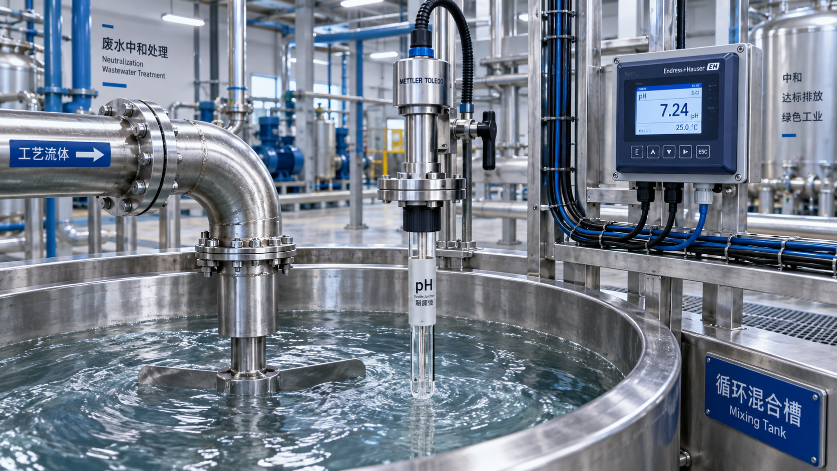
Continuous wastewater pH control fails less often because a meter lacks range and more often because the selected sensor, mounting arrangement, and maintenance concept do not match the chemistry of the stream. A standard glass electrode may read accurately in a clean laboratory sample yet become unstable, slow, or inaccessible when exposed to suspended solids, oil, sulfides, scale-forming salts, fibrous matter, high temperature, or periodic cleaning chemicals.
For process control, the selection question is not simply whether an instrument can measure pH 0–14. It is whether the complete measuring loop can provide a representative, stable signal for long enough to support neutralization control, discharge compliance, equipment protection, and operator decisions. That requires evaluating the sensor as part of the process, not as an isolated catalog item.
Begin with the control consequence, not the pH specification
The required measurement performance depends on what the pH value controls. A final-effluent monitor used to document compliance needs traceability, alarm integrity, and reliable records. A pH meter controlling acid or caustic dosing upstream of a biological treatment stage needs fast enough response and robust enough installation to prevent chemical overdosing and process excursions. A monitor protecting membranes, ion-exchange equipment, or downstream metal piping may need conservative alarm logic even where its absolute measurement uncertainty is less demanding.
This distinction matters because pH control has a nonlinear process relationship. Near neutrality, a small pH movement can represent a substantial change in hydrogen-ion activity, but the neutralization curve of an actual wastewater stream is governed by its buffering capacity, dissolved salts, reaction kinetics, mixing quality, and the strength of the reagent. A highly accurate sensor cannot compensate for poor mixing or an insufficient contact time between chemical addition and measurement.
Before specifying industrial pH meters, establish the operating pH band, normal and upset temperatures, pressure, solids loading, likely contaminants, flow pattern, cleaning chemicals, and required action when the signal becomes invalid. Also distinguish continuous exposure conditions from occasional events. A stream that is normally mild but periodically receives concentrated cleaning solution, solvent residue, or high-temperature wash water should be selected for those excursions if the measurement remains online during them.
Sensor construction determines whether the reading remains usable
Most industrial wastewater applications use glass pH electrodes combined with a reference system and an integrated temperature element. The glass membrane develops a voltage related to pH, while the reference junction provides the stable electrochemical comparison required for that voltage to be interpreted. In difficult wastewater, the reference junction is frequently the weak point: fouling, poisoning, clogging, dehydration, or contamination of the reference electrolyte can shift or destabilize the reading.
A sensor should therefore be assessed by its reference design, junction type, body material, pressure and temperature limits, and serviceability—not solely by nominal accuracy.
- Single versus double junction: A double-junction reference can provide an additional barrier between process contaminants and the reference system. It is often worth considering where sulfides, proteins, heavy-metal ions, or other compounds may interfere with or poison the reference electrolyte.
- Junction geometry: Open or annular junctions can resist clogging better in some dirty, high-solids streams, while conventional porous junctions may be adequate for cleaner flows. The right choice depends on whether solids are abrasive, adhesive, oily, or prone to crystallize.
- Gel-filled versus refillable reference systems: Gel-filled electrodes simplify routine handling and reduce leakage concerns, but refillable designs may offer maintenance advantages in demanding service where electrolyte condition must be managed. The decision should reflect site maintenance capability, not a universal preference.
- Sensor body material: Glass bodies can be vulnerable to mechanical impact. Plastic or high-performance polymer bodies may be preferable where vibration, installation handling, or solids create breakage risk, provided their chemical and temperature compatibility is confirmed.
- Flat-surface or bulb geometry: A protected or flat measurement surface may be more practical in coatings, sludge, and suspended-solid service than a conventional exposed bulb. However, it still requires cleaning and should not be assumed to be self-cleaning.
Low-conductivity water deserves separate attention. In dilute streams, the reference potential can become less stable and the sensor may respond slowly. Sensors designed for low-ionic-strength service, suitable installation arrangements, and longer stabilization allowances may be needed. Conversely, high-conductivity brines, plating waste, and concentrated chemical streams can create different risks, including junction contamination, temperature stress, and precipitation.
Response time is a system characteristic
Manufacturers may state a sensor response time under controlled conditions, but field response includes more than electrode chemistry. It also includes the time for wastewater to reach the measurement point, the degree of mixing after reagent injection, sample transport time where a bypass loop is used, coating removal, and transmitter filtering.
Locating a pH probe immediately downstream of acid or alkali injection can create an apparently responsive but misleading signal because the sensor sees local concentration pockets rather than the mixed bulk stream. Locating it too far downstream can introduce excessive delay, causing a dosing controller to react after the process has already moved beyond its target. The practical aim is a location with reliable mixing, adequate reaction time, and minimum avoidable transport delay.
Where the wastewater has a steep titration curve, a single control point may be unstable even with a good sensor. Split-range dosing, staged neutralization, deadband management, or a slower supervisory strategy may be more appropriate than increasing controller gain. Instrument selection should be coordinated with the control philosophy; a pH analyzer cannot resolve a chemically unstable dosing scheme by itself.
Choose the installation around the fluid, not around available pipework
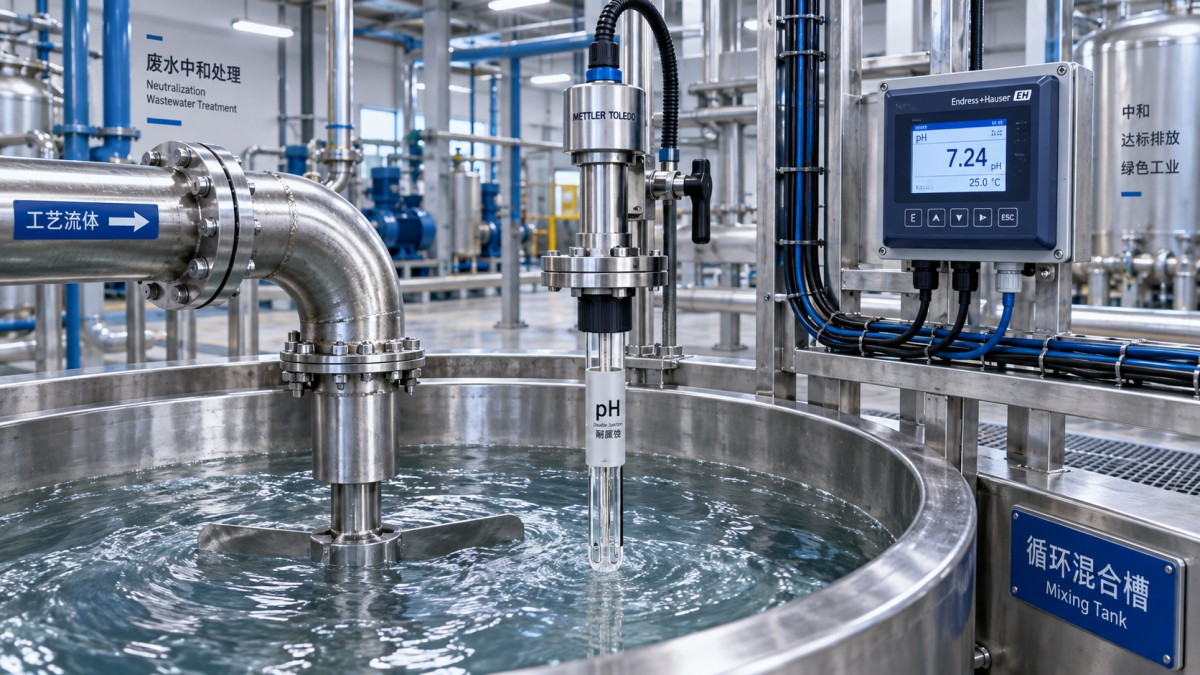
Insertion mounting in a flowing pipe is compact and often economical, but it only works when the probe remains wetted, protected from air bubbles, and accessible for removal. Low-flow sections, intermittent discharge pipes, and lines subject to gas release may expose the sensing surface to bubbles or incomplete immersion. Those conditions can produce noisy readings and accelerate drying of the reference junction.
An open channel or tank installation gives easier physical access, but the sensor must be placed where it sees representative liquid rather than floating debris, surface foam, chemical injection zones, or stagnant corners. In neutralization tanks, the most useful point is commonly associated with verified circulation and mixing rather than the geometric center of the vessel.
Retractable assemblies can reduce downtime where removal under process conditions is necessary. Their value depends on disciplined isolation, flushing, and safe withdrawal procedures. They should not be specified merely for convenience if the process contains hazardous fluids and the site cannot safely maintain the assembly. A bypass loop may improve access and permit conditioning, but it introduces sample lag, plugging risk, and another set of valves and wetted components to maintain.
For abrasive or fouling wastewater, mounting angle and probe protection matter. A sensor located in direct impingement from solids-laden flow may suffer mechanical damage; one placed in a dead leg will foul. The installation should permit inspection of the actual sensing surface without requiring extensive dismantling. If routine cleaning is expected, the physical arrangement must make that task realistic during normal plant operation.
Temperature compensation is necessary but not a cure for process effects
pH electrodes are temperature-sensitive, and integrated temperature measurement allows the transmitter to compensate the electrode slope according to temperature. This improves comparability when buffer calibration and process measurement occur at different temperatures. It does not correct for every temperature-driven change in the wastewater itself.
The actual pH of many solutions changes with temperature because chemical equilibria change. Temperature compensation corrects the electrode response, not necessarily the process value to a single reference condition. Where discharge limits or process setpoints are defined under a particular regulatory or laboratory convention, the measurement and reporting approach should be aligned with that requirement. It is important not to assume that an automatically temperature-compensated display represents a temperature-normalized chemical condition.
Temperature also affects sensor life. Repeated thermal cycling, operation near the upper temperature limit, and abrupt exposure to hot cleaning fluids can reduce electrode durability. If a line is periodically sanitized or cleaned in place, confirm both the continuous and transient temperature limits of the sensor, cable, seals, mounting hardware, and transmitter enclosure.
Calibration strategy should be designed before procurement
A pH loop is only as credible as its calibration and verification practice. Calibration buffers should bracket the normal operating range where feasible. For a neutralization process operating around pH 7, buffers near pH 7 and a second point on the acidic or alkaline side relevant to the control range are more useful than an arbitrary pair selected only because they are readily available.
Two-point calibration checks both offset and slope. Offset drift can indicate reference issues or contamination; declining slope can indicate aging glass, coating, damaged membranes, depleted electrolyte in applicable designs, or poor buffer condition. Modern transmitters may display diagnostics such as sensor slope, zero point, impedance, or predicted maintenance status. These values are useful only when maintenance personnel understand what action each condition requires and when field verification overrides an automated diagnostic.
Calibration frequency cannot be set responsibly from a generic interval alone. It should be based on process severity, historical drift, cleaning effectiveness, compliance criticality, and the consequence of a bad reading. In a stable, clean stream, frequent calibration may add little value. In a variable stream with oil, solids, or intermittent chemical discharge, the condition of the sensor may change materially between scheduled calibrations. A documented check using fresh buffers and appropriate cleaning is more informative than simply accepting a calibration routine because it is on a calendar.
Cleaning is part of the measurement design
Fouling changes the sensor’s contact with the process and can slow response long before the displayed value becomes obviously wrong. Typical deposits include mineral scale, biological film, oil, polymer, metal hydroxides, and fibrous solids. No single cleaning method suits all of them. Water rinsing may remove loose solids but not oil; acidic cleaning may dissolve scale but is unsuitable for every deposit or sensor material; detergent cleaning may be needed for organic films.
Automatic cleaning systems using spray water, air, brushes, or chemical wash can extend service intervals in some installations. They also create their own engineering requirements: cleaning fluid must not remain around the probe and distort the process value, the sequence must be coordinated with control hold logic, and the mechanism must be maintainable. A cleaning system that cannot be inspected or supplied reliably can become another failure point rather than a solution.
When the pH signal drives chemical dosing, the control system should define what happens during cleaning, calibration, sensor removal, and detected sensor fault. Holding the last value may be unsafe in one process and acceptable in another. A manual mode, a conservative fixed-dose mode, a permissive based on flow, or an alarm-and-stop response may be selected according to the process hazard and treatment capacity.
Assess the transmitter as an automation component
The analyzer transmitter must integrate with the plant’s control architecture and maintenance practice. Confirm the required output type—commonly 4–20 mA, digital fieldbus, Ethernet-based communication, or a combination—and determine whether isolated outputs are needed to reduce ground-loop and interference issues. Digital communication can provide sensor diagnostics and configuration data, but it does not remove the need for a reliable primary control signal and a documented fail-state.
In electrically noisy industrial areas, cable routing, shielding, grounding, surge protection, and enclosure rating can influence signal stability as much as the analyzer specification. Long sensor cable runs, moisture ingress in connectors, and incorrect grounding arrangements are recurring sources of erratic pH values. If a preamplified or digital sensor architecture is proposed, verify cable-length limits, connector environmental ratings, replacement compatibility, and whether the transmitter recognizes sensor-specific calibration data.
Where the installation is in a hazardous area, the entire measurement loop—not just the probe—must be evaluated against the applicable area classification and installation requirements. That may include the transmitter, power supply, barriers or isolators, cable glands, and maintenance procedure. A certificate for one component does not automatically establish compliance for the assembled loop.
Use lifecycle suitability as the final selection test
The lowest purchase price can be misleading when the process requires frequent sensor replacement, manual cleaning, unplanned calibration, or shutdown to access the probe. A technically sound evaluation compares expected service effort as well as instrument cost: sensor replacement interval under actual chemistry, ease of withdrawal, buffer and cleaning consumption, spare-parts availability, compatibility of replacement sensors, and the downtime consequence of failure.
A useful specification separates mandatory conditions from desirable features. Mandatory conditions may include chemical compatibility, minimum pressure and temperature ratings, required communications, enclosure protection, calibration capability, and access for maintenance. Desirable features may include advanced diagnostics, quick-connect fittings, automatic cleaning readiness, or digital sensor memory. This prevents feature-rich instruments from being selected when they do not solve the dominant field problem.
The strongest choice is usually the one that makes an accurate measurement maintainable in the installed location. For continuous wastewater process control, that means matching the electrode and reference system to the contaminants, proving that the sample is representative and well mixed, defining calibration and cleaning methods, and ensuring the automation system responds safely when the measurement is unavailable. Those conditions determine whether industrial pH meters support control decisions or merely generate a number on a screen.
Technical Specifications
- Air Handling Unit Supplier Checklist: Performance Data, Lead Times, and SupportAuthor :Environmental Engineering Director
- Buying Fiberglass Water Tanks Wholesale: Compare Quotes and Delivery CostsAuthor :Environmental Engineering Director
- Choosing an XLPE Power Cable Supplier: Test Reports, Traceability, and Lead TimesAuthor :Grid Infrastructure Analyst
Expert Insights

Chief Security Architect
Dr. Thorne specializes in the intersection of structural engineering and digital resilience. He has advised three G7 governments on industrial infrastructure security.
Related Analysis
- Oct 19, 2026Air Handling Unit Supplier Checklist: Performance Data, Lead Times, and SupportAuthor :Environmental Engineering Director
- Oct 18, 2026Buying Fiberglass Water Tanks Wholesale: Compare Quotes and Delivery CostsAuthor :Environmental Engineering Director
- Oct 17, 2026Choosing an XLPE Power Cable Supplier: Test Reports, Traceability, and Lead TimesAuthor :Grid Infrastructure Analyst
Core Sector // 01
Security & Safety
- Buying Fiberglass Water Tanks Wholesale: Compare Quotes and Delivery CostsAuthor :Environmental Engineering Director

- How to Select Industrial pH Meters for Continuous Wastewater Process ControlAuthor :Environmental Engineering Director

- How to Size a Rinse Fill Cap Machine for Your Bottle Format and Target OutputAuthor :Environmental Engineering Director

- How to Size a Heavy-Duty Submersible Sewage Pump for High-Solids Lift StationsAuthor :Environmental Engineering Director

- How to Size a Wafer Butterfly Valve for HVAC Chilled-Water and Heating LoopsAuthor :Environmental Engineering Director

- How Pressure Class and Joint Design Affect Long-Term Performance of Ductile Iron Pipes in Drainage InfrastructureAuthor :Environmental Engineering Director

- How Ductile Iron Pipe Joints Affect Installation Reliability and Leak ControlAuthor :Environmental Engineering Director

- How to Size Effluent Treatment Equipment for Variable Industrial Wastewater LoadsAuthor :Environmental Engineering Director