Ductile Iron Pipe Bedding: What to Check Before Lowering Pipe
Author
Date Published
Reading Time
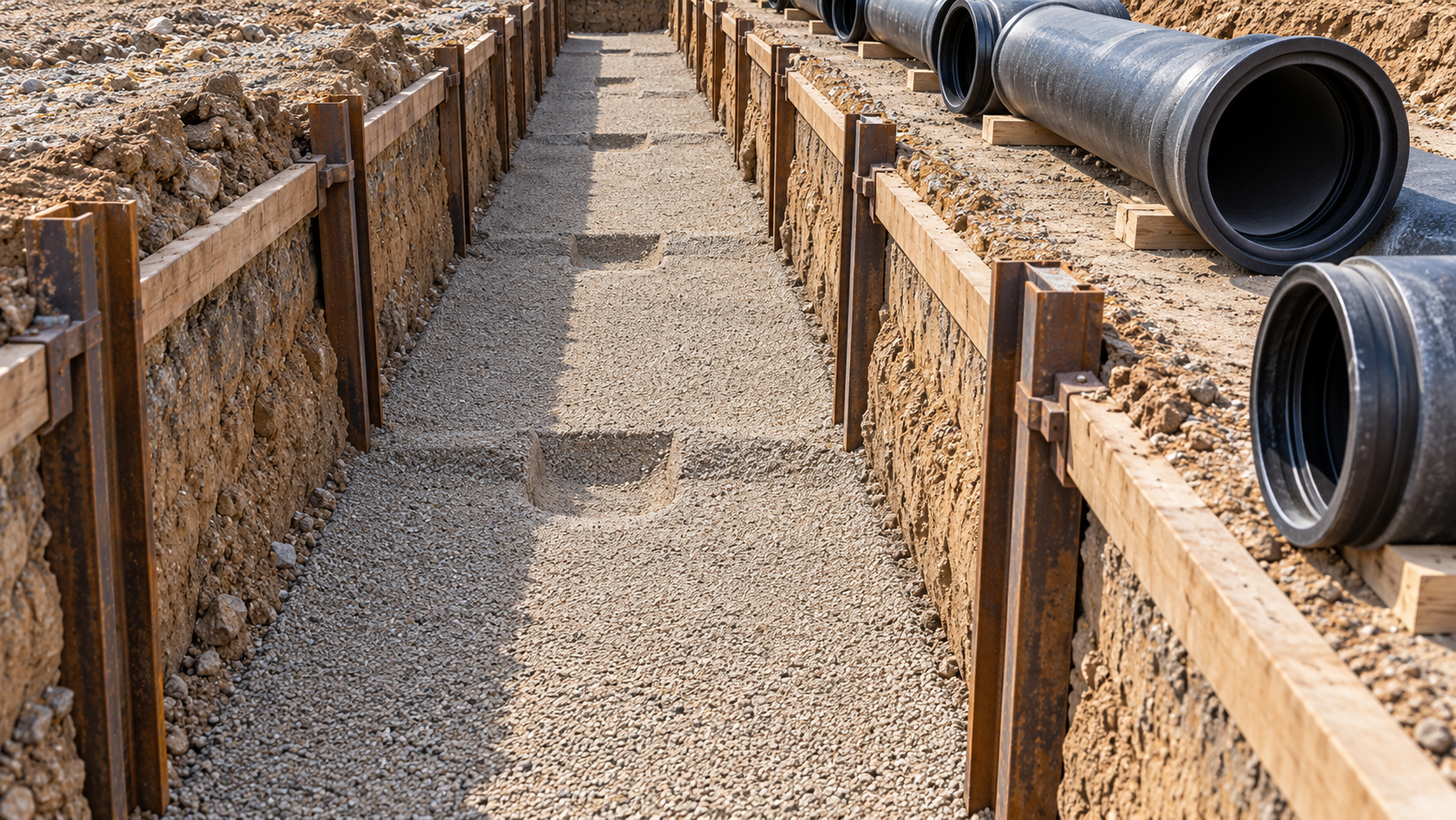
A trench can be on line and at the correct depth yet still be unfit to receive pipe. Soft pockets, projecting rock, poorly formed bell holes, or bedding disturbed by groundwater can leave a barrel supported unevenly. Once the pipe is lowered, these defects become harder to see and more expensive to correct.
Before lowering ductile iron pipe, verify that the trench foundation is stable, the specified bedding condition has been achieved, the barrel will receive the intended support, and the joint area has adequate clearance. Check that the crew can place and compact the subsequent embedment without displacing the pipe. These checks connect field installation to the assumptions used in structural design; they are not simply housekeeping tasks. ANSI/AWWA C600 addresses installation, while ANSI/AWWA C150/A21.50 provides the thickness-design framework and associated laying conditions.[1][2]
Start with the specified laying condition, not a generic bedding detail
“Bedding” is often used loosely to describe everything beneath and around a buried pipeline. For inspection purposes, distinguish the trench foundation, the prepared support beneath the barrel, and the material placed around the lower sides and above the pipe. A sound-looking surface layer cannot compensate for unstable soil underneath it.
The approved drawings and specification should identify the required installation condition. Before excavation reaches the pipe zone, the technical evaluator should reconcile that detail with the pipe design basis. The relevant questions include:
- What laying condition was assumed when the pipe thickness was selected?
- What bedding and embedment materials are permitted?
- Where are placement, compaction, and testing requirements defined?
- What action is required if rock, groundwater, or unsuitable soil is encountered?
- Who can approve a departure from the standard trench detail?
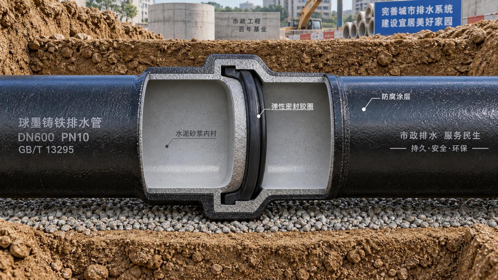
For a proposed ductile iron pipe supply, review the offered diameter, thickness designation, joint arrangement, and applicable product documentation alongside the installation detail. A product listing can support identification of the pipe category, but it does not establish whether a particular trench satisfies the project’s structural assumptions.
Do not treat similarly numbered laying conditions from different documents as interchangeable. Use the descriptions and requirements in the governing edition. If the design assumes a particular degree of side support, a field decision to omit the specified embedment or compaction requires engineering review rather than an informal acceptance.[1][2]
Confirm that the exposed foundation will remain stable
Inspect the actual trench bottom after excavation and any necessary water control, not just the ground encountered earlier. Look for pumping under foot traffic, localized yielding, remolded clay, organic material, loose spoil, and areas where excavation has disturbed otherwise competent soil. These observations identify conditions needing assessment; they do not replace specified geotechnical acceptance tests.
A useful question is whether the prepared foundation can retain its shape during bedding placement, pipe lowering, and embedment work. If granular material disappears into a soft base or the trench bottom deforms as equipment operates nearby, adding another thin layer of bedding may conceal the problem without resolving it.
Where unsuitable material is found, stop preparation in the affected area and obtain the approved treatment. Depending on the ground conditions, that treatment may involve additional excavation and replacement, separation materials, engineered stabilization, or another designed solution. The depth of removal and replacement detail should not be improvised by the installation crew. C600 addresses trench preparation and unsuitable foundation conditions; the project’s geotechnical recommendations should govern site-specific treatment.[1]
Rock and changes in ground stiffness deserve separate attention
In rock excavation, check that projections have been removed and the specified cushioning layer can be maintained beneath the barrel. A nominal bedding thickness measured at one convenient point does not demonstrate that clearance exists over an irregular rock surface.
Also examine transitions between rock and soil, or between ordinary trench foundation and structures. These locations may create abrupt changes in support stiffness. The appropriate transition detail depends on anticipated movement, joint behavior, and structural design. Concrete packing or encasement should not be introduced as an unreviewed field remedy.
Check bedding material and geometry together
Material approval and installed condition are different acceptance decisions. A delivery ticket may show that aggregate meets a grading specification, yet the placed layer may still contain segregated coarse particles, mud, frozen lumps, or debris picked up during handling.
Check the material against the project’s grading, particle-size, cleanliness, and placement requirements. Avoid assuming that one aggregate description is suitable for every installation. Material selection must account for placement around the pipe, the surrounding soil, groundwater behavior, and any exterior protection system. Where polyethylene encasement is specified, handling and installation should also follow ANSI/AWWA C105/A21.5 and the applicable manufacturer’s instructions.[3]
Bedding thickness should be checked at enough locations to reveal variation, especially near rock, sumps, previous over-excavation, and repaired soft spots. Record measurements against the specified detail rather than accepting the trench because its average depth appears adequate.
Provide barrel support without resting the pipe on its bells
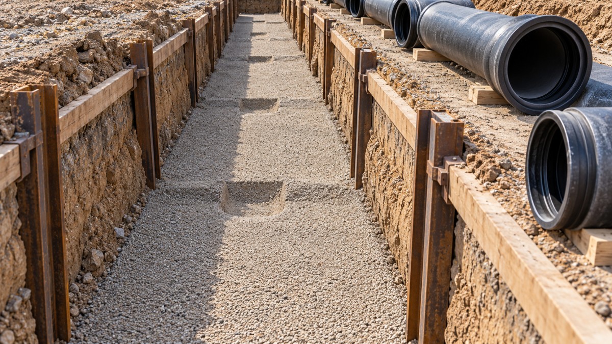
The intended load path is through the prepared support beneath the barrel and the surrounding embedment—not through isolated contact at the bells. Bell holes provide room for joint assembly while allowing the barrel to seat as specified. They should be positioned for the actual pipe lengths and joint locations, rather than excavated at assumed intervals.[1]
Before lowering, compare bell-hole positions with the laying sequence. Confirm that there is enough working clearance for the specified joint and that the excavation has not unnecessarily removed support from adjacent barrel sections. After jointing, these areas must remain accessible for completing the specified embedment.
A common temptation is to correct grade with timber, stones, or small hard packing pieces. Unless such supports are part of an engineered detail, they substitute point support for the intended bedding condition. Correct the prepared surface instead. If the installation requires a special support arrangement, obtain an approved detail before lowering the affected pipe.
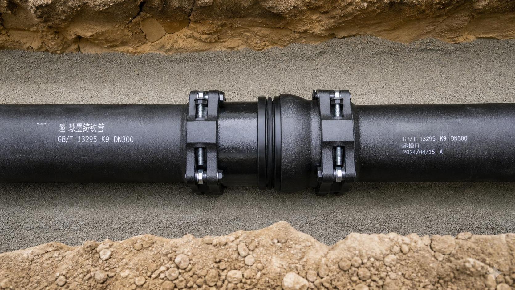
Curved alignments need another check: the trench and bedding must accommodate the planned joint deflection without forcing the barrel against the trench wall. Joint deflection limits and assembly sequences are product-specific. Verify them against the pipe manufacturer’s installation instructions; do not infer allowable movement from the space available in the trench.
Assess water control and trench safety before releasing the work area
Water can change an accepted bedding surface between inspection and pipe placement. Inflows may carry fines, erode a prepared layer, or soften exposed soil. Pumping can also disturb the foundation if the intake arrangement draws material from the pipe-support zone. The water-control method therefore needs to preserve the trench condition, not merely make the water level appear manageable.
Where bedding material and surrounding soil have significantly different particle distributions, assess whether migration or separation needs an engineered response. A geotextile is not an automatic cure: its filtration, separation, installation, and durability requirements must suit the ground and hydraulic conditions. Refer that decision to the project designer or geotechnical specialist.
In the United States, OSHA 29 CFR 1926.651(h) addresses water accumulation in excavations, and 1926.651(k) requires competent-person inspections under the conditions stated in that regulation. Protective-system requirements are addressed in 1926.652. These safety obligations are separate from bedding acceptance: a technically acceptable pipe foundation does not make an excavation safe to enter.[4]
Arrange inspections around the approved excavation-access and lifting procedures. Do not place an inspector beneath a suspended pipe to verify contact. Bedding inspection should occur before lowering; subsequent seating checks must use a safe method suited to the excavation and lift plan.
Verify that the next installation steps are achievable
The pre-lowering check should include the space and method needed to complete embedment. A trench may accommodate the pipe but leave insufficient working room for the specified placement and compaction equipment. Trench support can further restrict access, particularly around the lower sides of the barrel.
Ask how material will reach the haunch areas, how placement will be balanced, and how the required compaction will be achieved and verified. Acceptance should be based on the specified method or testing criteria—not on whether the exposed top surface looks firm. Changes to compaction equipment, lift thickness, or material require review where they affect the approved procedure.[1]
Check the planned sequence for withdrawing trench shields or other temporary support. The method should avoid disturbing the pipe and leaving unfilled spaces in the embedment. Where the excavation system conflicts with the specified trench detail, resolve that conflict before the pipe obstructs access.
Fittings, valves, restrained joints, and connections to structures may require separate support or restraint details. Ordinary bedding is not a substitute for the designed resistance to hydraulic thrust. Confirm that any required foundations, restraint components, and inspection access are coordinated with the pipe-laying sequence.
Use a documented hold point before lowering
A practical release record identifies the inspected trench section, the governing detail, foundation condition, bedding material, measured grade, bell-hole readiness, and unresolved exceptions. Include photographs before the pipe covers the support surface, along with material records and specified test results. Record who accepted corrective work and where it was performed.
The release should apply to the observed condition, not indefinitely to a length of trench. Rainfall, groundwater inflow, movement of trench support, or disturbance by equipment can justify reinspection before placement.
If the crew cannot demonstrate stable foundation support, the specified bedding geometry, and a workable embedment method, the section is not ready for lowering. Resolving those uncertainties while the trench bottom remains visible is more reliable than trying to infer the support condition after the pipe is installed.
Sources
- [1] American Water Works Association, ANSI/AWWA C600, Installation of Ductile-Iron Water Mains and Their Appurtenances. Use the edition adopted by the project.
- [2] American Water Works Association, ANSI/AWWA C150/A21.50, Thickness Design of Ductile-Iron Pipe. Consult the adopted edition for design assumptions and laying-condition descriptions.
- [3] American Water Works Association, ANSI/AWWA C105/A21.5, Polyethylene Encasement for Ductile-Iron Pipe Systems.
- [4] U.S. Occupational Safety and Health Administration, 29 CFR Part 1926, Subpart P—Excavations; specifically sections 1926.651(h), 1926.651(k), and 1926.652.
Technical Specifications
- US Commerce Opens Changed Circumstances Review of Mexican Heavy-Walled Rectangular Welded Carbon Steel PipeAuthor :Heavy Industry Strategist
- Selecting Flexible Copper Busbars for Switchgear: Current Rating and Bend RadiusAuthor :Grid Infrastructure Analyst
- Outdoor Vacuum Circuit Breaker Selection: Voltage, Fault Duty, and Site ConditionsAuthor :Grid Infrastructure Analyst
Expert Insights

Chief Security Architect
Dr. Thorne specializes in the intersection of structural engineering and digital resilience. He has advised three G7 governments on industrial infrastructure security.
Related Analysis
- Oct 26, 2026US Commerce Opens Changed Circumstances Review of Mexican Heavy-Walled Rectangular Welded Carbon Steel PipeAuthor :Heavy Industry Strategist
- Oct 26, 2026Selecting Flexible Copper Busbars for Switchgear: Current Rating and Bend RadiusAuthor :Grid Infrastructure Analyst
- Oct 25, 2026Outdoor Vacuum Circuit Breaker Selection: Voltage, Fault Duty, and Site ConditionsAuthor :Grid Infrastructure Analyst
Core Sector // 01
Security & Safety
- Ductile Iron Pipe Bedding: What to Check Before Lowering PipeAuthor :Environmental Engineering Director

- Buying Fiberglass Water Tanks Wholesale: Compare Quotes and Delivery CostsAuthor :Environmental Engineering Director

- How to Select Industrial pH Meters for Continuous Wastewater Process ControlAuthor :Environmental Engineering Director

- How to Size a Rinse Fill Cap Machine for Your Bottle Format and Target OutputAuthor :Environmental Engineering Director

- How to Size a Heavy-Duty Submersible Sewage Pump for High-Solids Lift StationsAuthor :Environmental Engineering Director

- How to Size a Wafer Butterfly Valve for HVAC Chilled-Water and Heating LoopsAuthor :Environmental Engineering Director

- How Pressure Class and Joint Design Affect Long-Term Performance of Ductile Iron Pipes in Drainage InfrastructureAuthor :Environmental Engineering Director

- How Ductile Iron Pipe Joints Affect Installation Reliability and Leak ControlAuthor :Environmental Engineering Director