Selecting Flexible Copper Busbars for Switchgear: Current Rating and Bend Radius
Author
Date Published
Reading Time
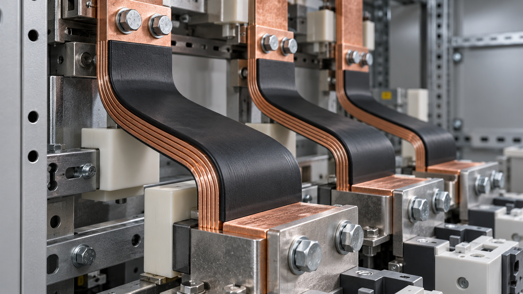
Flexible copper busbars are suitable for a switchgear connection when their current-carrying capability is supported by the intended enclosure conditions and their permitted bend geometry fits the available space. A catalog ampere rating and a drawing showing that the conductor fits between terminals are useful starting points, but neither establishes that the installed connection will operate within its thermal and mechanical limits.
For technical evaluation, approval should rest on three linked checks: the rating applies to the proposed installation, the busbar can be formed without damaging its conductor or insulation, and the finished assembly preserves acceptable joint performance, electrical clearances, and fault withstand. Increasing conductor size may improve thermal performance while making routing more difficult. Tightening a bend to recover space can introduce a different failure mechanism. These decisions need to be assessed together.
Establish which flexible construction is being evaluated
“Flexible copper busbar” can describe insulated stacks of thin copper laminations, assemblies with consolidated ends and a flexible central section, or braided connections. Their flexibility, termination arrangements, heat dissipation, and response to repeated movement differ. Two products with the same nominal copper cross-sectional area should not be treated as interchangeable without reviewing their construction and application data.
For laminated designs, individual foil thickness and the ability of layers to move relative to one another influence forming behavior. End consolidation, insulation, and the length available for bending can restrict that movement. Braided conductors have different geometry and termination characteristics. Establish whether the connection needs only installation flexibility or must accommodate vibration, thermal expansion, or repeated displacement during service. A product that can be bent into position does not automatically have a qualified fatigue life.
Read the current rating as a set of conditions
A current rating describes performance under specified conditions. Before comparing suppliers, obtain the ambient temperature, permitted temperature rise or limiting temperature, mounting orientation, conductor arrangement, enclosure conditions, and termination configuration behind each rating. Check whether the data apply to the exact construction and size being offered. A rating without these conditions provides too little information for a defensible selection.
The relevant ambient is the air temperature surrounding the connection inside the switchgear. Room temperature alone can understate this exposure. Nearby circuit breakers, adjacent conductors, compartment partitions, and restricted airflow can raise local temperatures. If cooling depends on fans, establish which operating conditions the assembly must support following a fan failure. A rating derived under open-air conditions cannot simply be transferred to a crowded compartment.
Temperature limits also extend beyond the copper. Insulation, terminal interfaces, connected equipment, and other assembly components may impose lower allowable temperatures. Check how the supplier defines its limit and which location governs it. A conductor that stays below its insulation temperature limit can still create an unacceptable temperature at a circuit-breaker terminal or bolted connection.
Current density can help compare preliminary options, but it should not become the acceptance criterion. Dividing current by copper area does not capture surface area, airflow, insulation, proximity to other phases, or connection resistance. Likewise, a simple square-root correction based on allowable temperature rise can overlook changes in resistance and heat transfer. Use manufacturer-supported correction methods within their stated scope; otherwise, seek application-specific thermal evidence.
At AC, conductor geometry, frequency, and proximity to other conductors can affect losses through skin and proximity effects. Parallel paths also require attention to impedance and current sharing. At DC, the AC effects may be absent, but thermal conditions and connection quality still govern performance. Where the duty includes significant ripple, harmonics, or intermittent overloads, provide that information rather than describing the application only by its nominal current.
A useful rating comparison should therefore answer:
- What continuous current and overload duty must the connection carry?
- What local ambient temperature and cooling conditions will it experience?
- Does the evidence cover the proposed orientation, spacing, and number of parallel conductors?
- Which conductor, insulation, joint, or equipment temperature limit controls acceptance?
- How will differences between the documented arrangement and the installed assembly be assessed?
Consider two candidates: one has a higher published rating in free air; the other has a lower published rating supported by data for a comparable enclosed arrangement. The first candidate is not necessarily unsuitable, but its larger catalog number does not establish a thermal advantage in the switchgear. The second may offer a stronger basis for evaluation if its documented conditions match the installation more closely. Compare the applicability of the evidence before comparing the headline ratings.
Treat bend radius as a product-specific installation limit
Minimum bend radius depends on construction and bend direction. Obtain the requirement for the exact part, including whether the radius is measured at the inside surface, conductor centerline, or another reference. A radius on a drawing is ambiguous without that definition. Also distinguish the permitted radius of the copper assembly from the bending limits of its insulation; satisfying one does not necessarily satisfy the other.
A laminated conductor generally bends more readily through its thin dimension than across its width, but the permitted directions must come from the manufacturer. Edgewise bending, twisting, and compound bends may impose restrictions beyond a simple flat bend. Instructions should identify any straight length required beside the termination and any prohibited forming zone near consolidated ends, holes, or insulation transitions. Do not infer these limits from a photograph or a broadly similar product.
The relationship between thickness and bending strain explains why a generic radius rule can be misleading. Thin individual foils can accommodate bending differently from a solid bar of the same total thickness when the layers can move. That movement may be constrained near joined ends or by the surrounding construction. Applying a solid-bar rule to the overall stack, or assuming that foil flexibility eliminates a minimum radius, can both produce poor decisions.
Evaluate the full routing envelope, including the space needed to make and install the bend. A connection can appear to fit in its final position yet require excessive deformation to pass between components. Allow for terminal alignment, assembly tolerances, tools, and any movement expected in service. Avoid using terminal bolts to pull a misaligned conductor into place: doing so can leave sustained loads on equipment terminals and alter the intended contact conditions.
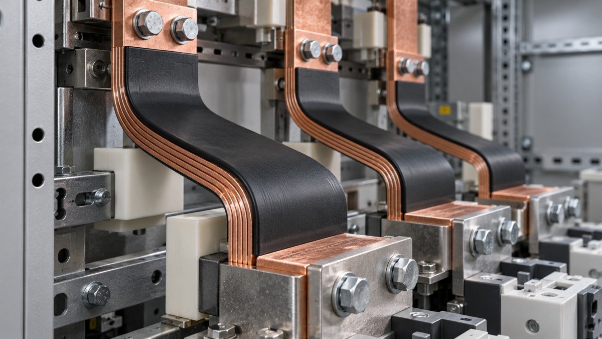
A useful routing drawing identifies the bend plane, radius reference, straight termination zones, and conductor position relative to adjacent phases and grounded metal. It should also show the conductor’s outer envelope, including insulation, rather than only its centerline. This makes clearance reviews more meaningful and helps distinguish a controlled forming operation from an installer improvising a shape inside the enclosure.
Where repeated movement is required, ask for evidence covering the displacement, direction, frequency, and expected number of cycles. A minimum installation bend radius does not define continuous-flex capability. Repeated correction during assembly can also accumulate deformation, particularly near terminations. Forming instructions should specify acceptable tools and methods, limits on rebending, and rejection criteria for damaged insulation, displaced laminations, or distorted contact ends.
Check the installed connection as an electrical and mechanical assembly
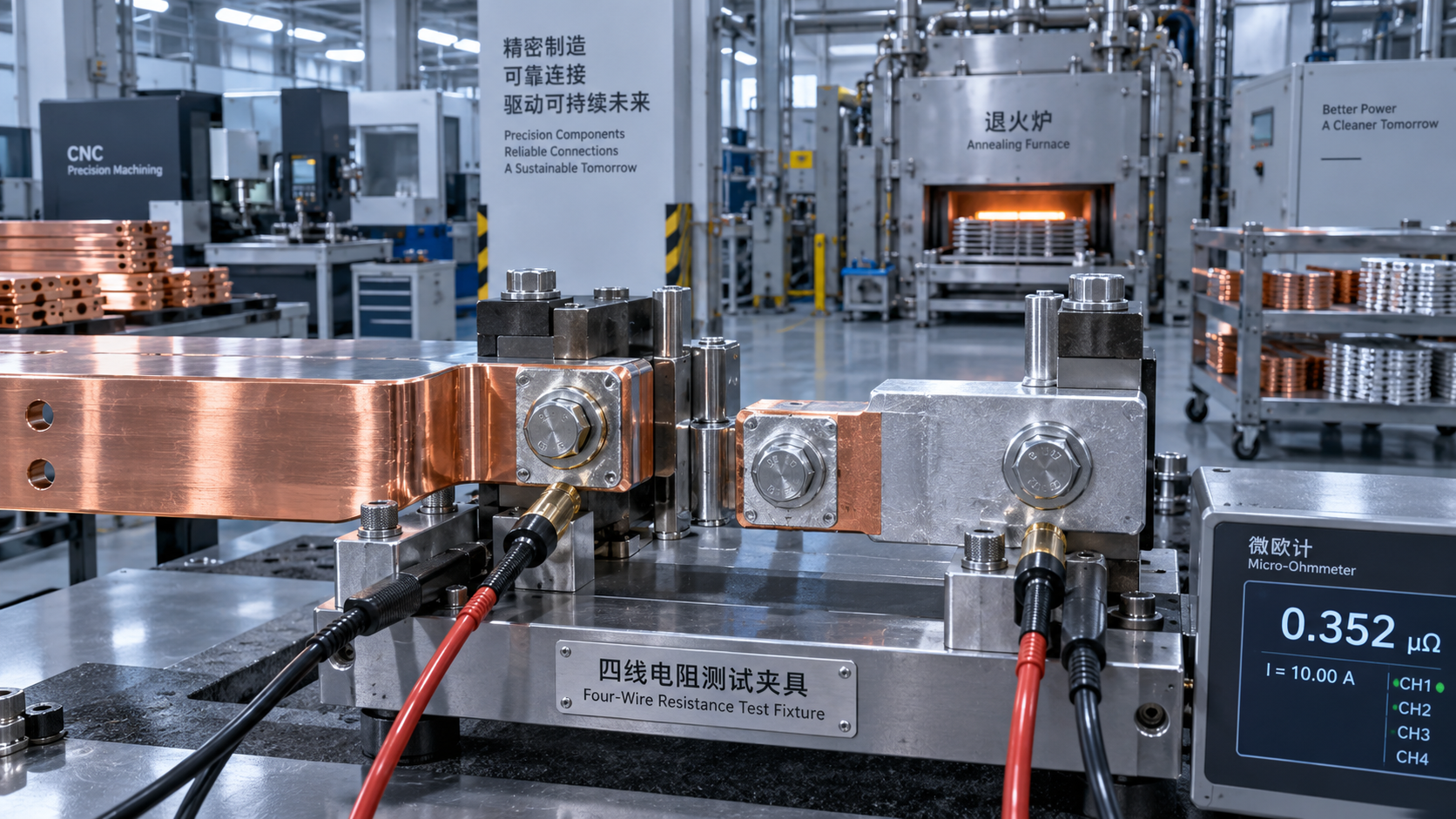
Conductor losses and joint losses contribute to the same thermal problem. Joint resistance produces local heating according to current squared multiplied by resistance, so a poorly controlled interface can dominate an otherwise adequate conductor design. Review the contact area, surface finish, mating materials, fasteners, washers, tightening requirements, and surface preparation as a defined connection system. Use the applicable equipment and busbar instructions to resolve compatibility.
Mechanical fit matters at this interface. Contact faces should seat as intended without bending the terminal pad or forcing the flexible section against nearby components. Check whether the proposed arrangement introduces leverage on a breaker terminal or other equipment connection. Flexibility can reduce the transfer of movement, but it does not remove the need to assess terminal loads, support locations, and installation tolerances.
Insulation around the flexible span does not settle every electrical-spacing question. Exposed ends, fasteners, neighboring phases, and grounded enclosure parts remain part of the assessment. Required clearances and creepage distances depend on the applicable assembly requirements and service conditions. Routing must preserve them after installation, including where a bend brings a conductor edge closer to metalwork. Consider movement during normal operation and fault conditions as part of that review.
Short-circuit withstand is a separate acceptance check from continuous current capacity. Obtain the prospective fault conditions and the protective device’s clearing characteristics, then assess the connection’s thermal and mechanical withstand within the assembly. A flexible conductor can move under electromagnetic forces. Its supports, free span, terminations, and proximity to other parts therefore matter. A continuous-current rating alone gives no assurance that the proposed arrangement will survive the specified fault duty.
Specify the evidence needed for approval
For low-voltage switchgear, the applicable IEC 61439 requirements or the relevant North American assembly standard may form part of the verification framework, depending on the equipment and market. The exact route should be established for the assembly being supplied. A component certificate or recognition supports only the scope it covers; it does not establish compliance of every enclosure, routing arrangement, or termination in which the component might be installed.
A practical submission should include a dimensioned part drawing, conductor construction and copper area, insulation characteristics, rating conditions, forming instructions, and termination requirements. It should also identify the evidence supporting temperature rise and fault withstand in the proposed application. Where calculations or comparison with an existing design support approval, the submission should explain their applicability and limitations. A product datasheet by itself may leave the most consequential installation assumptions unresolved.
If application testing is needed, agree on the representative arrangement before testing begins. It should capture the enclosure, heat-producing equipment, conductor routing, connections, cooling conditions, and loading relevant to the assessment. Measure temperatures at locations capable of revealing local problems, including critical joints and terminals. Evaluate results against the applicable limits and test method, with sufficient time for the required thermal condition to be established.
Approve the busbar configuration together with its installation conditions. Record the accepted part, routing, minimum radii, connection details, supports, cooling assumptions, and verification basis. Changes to conductor construction, insulation, terminal hardware, or enclosure layout can affect that basis even when nominal copper area remains unchanged. If a candidate needs a tighter bend than its instructions permit or relies on a rating that cannot be related to the enclosure, revise the selection or layout before releasing it for manufacture.
Technical Specifications
- US Commerce Opens Changed Circumstances Review of Mexican Heavy-Walled Rectangular Welded Carbon Steel PipeAuthor :Heavy Industry Strategist
- Selecting Flexible Copper Busbars for Switchgear: Current Rating and Bend RadiusAuthor :Grid Infrastructure Analyst
- Outdoor Vacuum Circuit Breaker Selection: Voltage, Fault Duty, and Site ConditionsAuthor :Grid Infrastructure Analyst
Expert Insights

Chief Security Architect
Dr. Thorne specializes in the intersection of structural engineering and digital resilience. He has advised three G7 governments on industrial infrastructure security.
Related Analysis
- Oct 26, 2026US Commerce Opens Changed Circumstances Review of Mexican Heavy-Walled Rectangular Welded Carbon Steel PipeAuthor :Heavy Industry Strategist
- Oct 26, 2026Selecting Flexible Copper Busbars for Switchgear: Current Rating and Bend RadiusAuthor :Grid Infrastructure Analyst
- Oct 25, 2026Outdoor Vacuum Circuit Breaker Selection: Voltage, Fault Duty, and Site ConditionsAuthor :Grid Infrastructure Analyst
Core Sector // 01
Security & Safety
- Selecting Flexible Copper Busbars for Switchgear: Current Rating and Bend RadiusAuthor :Grid Infrastructure Analyst

- Niagara Power Transformer Begins $71 Million-Plus Buffalo ExpansionAuthor :Grid Infrastructure Analyst

- Choosing a Step-Down Transformer Supplier: Test Reports, Lead Times, and WarrantyAuthor :Grid Infrastructure Analyst

- Metallurgy Processes That Improve Conductivity and Reliability in Power Grid ComponentsAuthor :Grid Infrastructure Analyst

- How to Size a UPS for Server Rooms: Load, Runtime, and Redundancy FactorsAuthor :Grid Infrastructure Analyst

- How to Choose a Step-Down Transformer for a Control Panel: Key Sizing FactorsAuthor :Grid Infrastructure Analyst

- How Often Should Overseas Power Systems Undergo Safety Inspections?Author :Grid Infrastructure Analyst

- How to Choose Panels for Extreme-Cold Industrial Sites?Author :Grid Infrastructure Analyst