Outdoor Vacuum Circuit Breaker Selection: Voltage, Fault Duty, and Site Conditions
Author
Date Published
Reading Time
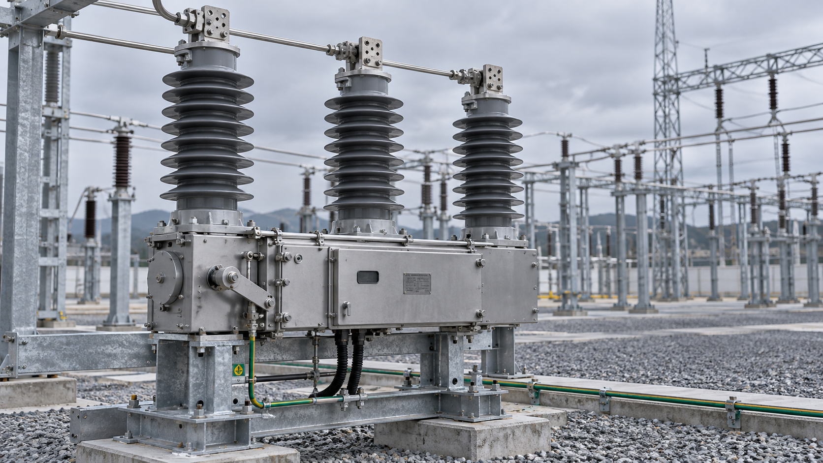
An outdoor vacuum circuit breaker should be selected against the network’s maximum operating voltage, calculated fault duty, required switching sequence, and actual site conditions—not nominal voltage alone. A breaker can have adequate short-circuit breaking capacity yet remain unsuitable because its insulation level, transient recovery voltage capability, closing duty, or environmental qualification does not match the installation.
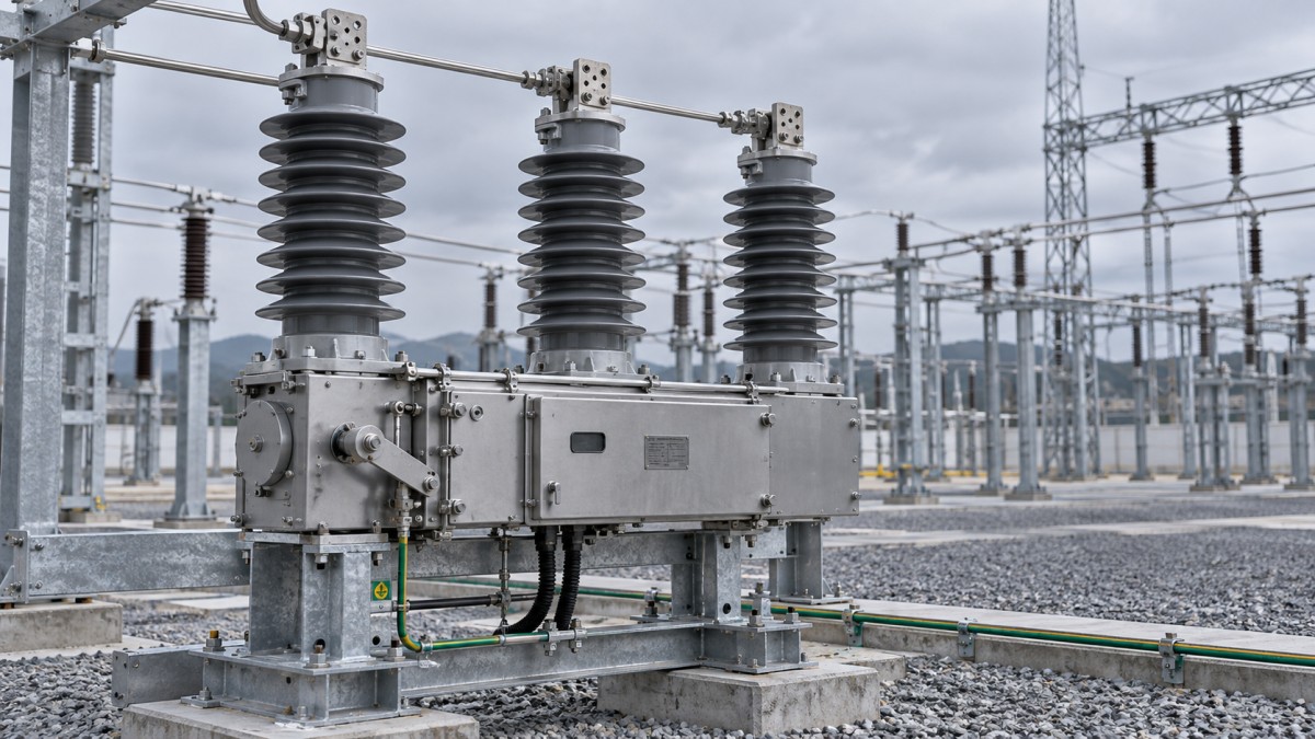
The essential distinction is between the vacuum interrupter’s capability and the performance of the complete outdoor assembly. Vacuum provides the interruption medium; it does not eliminate external flashover, terminal overheating, mechanism failure, or loss of control power. A defensible selection therefore connects each specified rating to a system study, installation condition, or documented operating requirement.
Establish the equipment boundary before comparing ratings
“Outdoor vacuum circuit breaker” can describe a standalone breaker, a breaker integrated into outdoor switchgear, or equipment offered with automatic reclosing controls. These configurations do not necessarily have the same qualification requirements or functional scope.
Define whether the supply includes current and voltage sensors, protection relays, a control cabinet, auxiliary power, surge arresters, disconnectors, and supporting steelwork. A breaker is not automatically an isolating device: maintenance isolation and earthing arrangements must be assessed separately. Likewise, an enclosure’s ingress protection rating does not establish the dielectric suitability of exposed bushings.
For IEC-based projects, IEC 62271-100 addresses alternating-current circuit breakers, with IEC 62271-1 providing common specifications. An integrated metal-enclosed assembly may also fall within IEC 62271-200, depending on its voltage and construction. IEEE-based specifications commonly reference IEEE C37.04 for ratings and requirements and IEEE C37.09 for test procedures. Automatic circuit reclosers have a separate standards framework, including IEC 62271-111/IEEE C37.60.
Specify the applicable editions and equipment category. “IEC compliant,” a CE marking, or an ISO management-system certificate is not a substitute for evidence that the offered breaker meets the required electrical duties.
Voltage selection is an insulation-coordination decision
Start with the highest system operating voltage at the installation, including permitted operating variations. Select an equipment rated maximum voltage that covers that value under the applicable standard. A nominal network designation alone is insufficient, particularly when comparing equipment specified under different IEC and IEEE rating conventions.
The voltage assessment must also establish power-frequency withstand and lightning impulse withstand levels. These ratings address different electrical stresses and cannot be inferred solely from the breaker’s voltage class. System earthing, overhead-line exposure, connected cable circuits, surge-arrester placement, and terminal clearances all affect insulation coordination.
Compare equivalent ratings rather than treating similarly positioned catalogue values as interchangeable. IEC lightning impulse withstand voltage and IEEE basic lightning impulse insulation level serve related purposes, but acceptance still depends on the applicable test definitions, configuration, and project requirements.
Surge arresters require particular attention. Their protective characteristics must coordinate with equipment withstand levels, while their continuous operating voltage and temporary-overvoltage capability must suit the network earthing arrangement. An arrester selected too low can be overstressed during a sustained earth fault; one selected too high may provide inadequate protection.
External insulation must be assessed in its installed geometry. Phase spacing, phase-to-earth clearance, terminal connectors, support structures, and adjacent equipment can undermine an otherwise adequate factory rating. Confirm whether dielectric evidence covers the complete pole assembly and the proposed mounting arrangement, rather than only the vacuum bottle.
Fault duty requires more than a symmetrical kA value
The short-circuit study should represent the network configuration expected during the equipment’s service period. Include credible operating states, parallel transformers, motor contribution, and planned generation or network reinforcement. Converter-connected sources require appropriate fault models; their contribution should not simply be treated as that of conventional rotating machines.
The resulting duty must be matched against several distinct breaker capabilities:
A high system X/R ratio produces a more slowly decaying DC component. Consequently, a breaker with an apparently adequate symmetrical breaking rating may require additional assessment if the network’s asymmetry exceeds the basis of its qualification. Compare the study assumptions with the manufacturer’s tested duty, including contact-parting time and the applicable DC time constant.
Making current should not be calculated using a universal multiplier detached from the governing standard and network conditions. Frequency, X/R ratio, and rating conventions affect the relationship between symmetrical RMS current and peak duty.
Short-time withstand duration must also agree with the protection scheme. If upstream backup protection clears a fault later than the breaker assembly’s qualified duration, adequate instantaneous breaking capacity does not resolve the mismatch.
Recovery voltage and switching applications can change the result
Transient recovery voltage, or TRV, is the voltage appearing across the breaker contacts following current interruption. Its magnitude and rate of rise depend on the surrounding circuit. Terminal faults, transformer-limited faults, and short-line faults where applicable can impose different stresses. A nameplate breaking-current rating is therefore not evidence of suitability for every circuit with that fault level.
Identify duties involving capacitor banks, unloaded cables, transformers, motors, or reactors. Capacitive switching requires relevant capacitive-current and restrike-performance evidence; back-to-back capacitor banks also introduce high-frequency inrush duty. Switching small inductive currents can produce overvoltages through current chopping and reignition, requiring application-specific assessment and, where justified, surge protection.
For generator-connected applications, determine whether generator-circuit-breaker requirements apply. A general distribution breaker should not be assumed suitable merely because its voltage and fault-current ratings appear sufficient.
Match operating duty to the protection philosophy
The specified operating sequence must reflect how the network will actually trip and reclose. The sequence notation defines opening, closing-opening operations, and the intervals between them. Verify the complete sequence rather than accepting a general claim of “reclosing capability.” A breaker may meet one sequence without being qualified for a faster sequence or additional close-open operations.
Automatic reclosing requires coordination between the breaker, mechanism, stored-energy system, controller, and protection settings. The mechanism must have sufficient energy available at each required operation, including under minimum auxiliary-voltage conditions. Closing onto a persistent fault must remain within the specified making and subsequent breaking duties.
Mechanical endurance and electrical endurance are separate considerations. A high no-load operation count does not establish the number of rated fault interruptions available before inspection or maintenance. Request the applicable endurance classification, supporting test evidence, and maintenance criteria for the proposed duty.
Protection coordination also depends on total clearing time, not relay operating time alone. Relay processing, output contacts, trip-circuit response, mechanism motion, and arcing time all contribute. Confirm CT performance at the relevant fault levels: saturation can delay or distort protection response even when the breaker itself is adequately rated.
Site conditions can invalidate standard-service ratings
Catalogue ratings are conditional on defined service conditions. The installation specification should state altitude, ambient temperature range, solar exposure, pollution severity, humidity, condensation risk, and mechanical environmental loads. “Outdoor suitable” is too broad to establish acceptance.
Altitude affects the assembly differently from the interrupter
Reduced air density at altitude lowers the dielectric strength of external air insulation and affects cooling. The sealed vacuum interrupter does not experience the same atmospheric dielectric reduction, but its bushings, terminal clearances, supports, and current-carrying assembly still require assessment.
IEC normal service conditions generally use an altitude limit of 1,000 m; installations above the applicable reference conditions require specific evaluation. Obtain the manufacturer’s insulation-correction method and continuous-current assessment. Increasing the voltage class without checking clearances, thermal performance, and installation geometry is not a complete solution.
Pollution performance depends on the contamination mechanism
Salt deposition, industrial contamination, and dust that becomes conductive when wet can create surface leakage and flashover paths. Creepage distance matters, but it is not an independent guarantee of performance. Insulator profile, material, diameter, orientation, wetting conditions, and maintenance access also influence suitability.
Use a site-pollution assessment and an appropriate insulation-selection method, such as the relevant IEC 60815 guidance. Evaluate polymeric and porcelain insulation against the actual exposure rather than assuming either material is universally superior. Housing erosion, tracking resistance, corrosion, and cleaning requirements belong in the comparison.
Temperature and moisture affect dependable operation
Continuous-current capability must account for the specified ambient conditions, solar heating, conductor connections, and any enclosure restrictions. A temperature-rise test conducted under defined conditions does not automatically establish unrestricted performance at a hotter site.
At low temperature, mechanism lubrication, seals, batteries, and control electronics can become limiting components. Require operating evidence covering the declared minimum temperature and auxiliary-voltage range, not merely a storage-temperature declaration.
Rain protection does not eliminate internal condensation. Daily temperature cycling can wet terminal blocks and electronics inside an otherwise sealed control cabinet. Assess heaters or other condensation controls, drainage, cable entries, and the availability of their power supply. The complete trip path must remain functional under the specified moisture conditions.
Wind, ice, seismic loading, and conductor forces also need defined limits. Supporting frames and foundations must be compatible with the qualified breaker arrangement; an equipment-level seismic claim does not automatically validate a different mounting structure.
Resolve evidence gaps before accepting the selection
Supplier comparisons become meaningful when every offer is evaluated against the same duty schedule. Record the required value, offered rating, supporting document, and any restriction or deviation. Separate mandatory capabilities from optional features so that an attractive control package cannot obscure an electrical shortfall.
Type-test evidence should be traceable to the offered design. Check the interrupter, pole construction, mechanism, insulation arrangement, and relevant accessories. Where a tested design differs, request the technical basis for extending the results. A report for an interrupter alone does not demonstrate complete-breaker performance.
Routine test records and factory acceptance testing serve a different purpose from type tests. They can verify production quality, wiring, timing, contact resistance, mechanical operation, and agreed functional checks, but they do not recreate full short-circuit qualification. Acceptance should include the specified trip and close supply limits, interlocks, alarms, and interfaces.
The strongest selection is the breaker whose documented capability covers the actual network and site duties with a justified allowance for uncertainty and planned changes. Any unresolved mismatch—whether in TRV, fault duration, insulation correction, or minimum-temperature operation—should remain an explicit technical exception rather than disappearing behind a higher headline voltage or kA rating.
Technical Specifications
- Outdoor Vacuum Circuit Breaker Selection: Voltage, Fault Duty, and Site ConditionsAuthor :Grid Infrastructure Analyst
- Niagara Power Transformer Begins $71 Million-Plus Buffalo ExpansionAuthor :Grid Infrastructure Analyst
- Buying Lab Incubators Wholesale: MOQs, Lead Times, and Warranty TermsAuthor :Precision Metrology Expert
Expert Insights

Chief Security Architect
Dr. Thorne specializes in the intersection of structural engineering and digital resilience. He has advised three G7 governments on industrial infrastructure security.
Related Analysis
- Oct 25, 2026Outdoor Vacuum Circuit Breaker Selection: Voltage, Fault Duty, and Site ConditionsAuthor :Grid Infrastructure Analyst
- Oct 24, 2026Niagara Power Transformer Begins $71 Million-Plus Buffalo ExpansionAuthor :Grid Infrastructure Analyst
- Oct 24, 2026Buying Lab Incubators Wholesale: MOQs, Lead Times, and Warranty TermsAuthor :Precision Metrology Expert
Core Sector // 01
Security & Safety
- Outdoor Vacuum Circuit Breaker Selection: Voltage, Fault Duty, and Site ConditionsAuthor :Grid Infrastructure Analyst

- Choosing a Surge Protection Device Factory: Testing and Traceability ChecksAuthor :Grid Infrastructure Analyst

- Can SPDs Handle Repeated Voltage Spikes in Tropical Grids?Author :Grid Infrastructure Analyst

- How to Evaluate IEC-Compliant Power Protection Devices for Industrial PanelsAuthor :Grid Infrastructure Analyst

- How to Choose Smart Industrial Control Equipment for Harsh Plant EnvironmentsAuthor :Grid Infrastructure Analyst

- EU EMC Update Triggers Re-Certification for BreakersAuthor :Grid Infrastructure Analyst

- How to Select the Right SPD for Solar Inverter Protection in PV Systems?Author :Grid Infrastructure Analyst

- Industrial Valve Systems Factory Checklist: What Buyers Should Verify Before OrderingAuthor :Grid Infrastructure Analyst