IEC-Compliant Power Infrastructure: Key Design and Verification Requirements
Author
Date Published
Reading Time

IEC-compliant power infrastructure is not a documentation exercise added at the end of an electrical project. For technical evaluators, it is a way to determine whether a system can remain safe, selective, maintainable, and operational through its intended service life. The distinction matters because industrial facilities rarely fail at the level of a single component. Failures usually emerge at the interfaces: between utility supply and site distribution, between switchboard ratings and actual fault levels, between protection settings and changed operating conditions, or between a supplier's declaration and the evidence needed for acceptance.
Projects described as “IEC compliant” often contain a mixture of correctly specified equipment, incomplete system studies, legacy assets, and site-specific requirements. A circuit breaker may carry an IEC marking while the assembled panel has not been verified for its final configuration. A transformer may meet its product standard, while the grounding arrangement or protection coordination around it remains unsuitable for the installation. Technical evaluation therefore has to move beyond asking whether a product is IEC-certified. The more useful question is whether the complete power infrastructure solution has been designed, verified, installed, and documented against the IEC requirements relevant to its actual duty.
Why compliance has become an operational issue
Industrial power systems are being asked to do more than distribute electricity. Electrification of process heat, variable-speed drives, onsite generation, battery energy storage, data-intensive control systems, and tighter uptime commitments have all increased the consequences of poor electrical design. In many facilities, the available fault current, harmonic profile, load diversity, and operating modes are no longer stable assumptions established once during design.
This changes the compliance discussion. IEC standards provide a common technical language for equipment and systems, but compliance does not automatically guarantee availability or suitability. A design can meet a minimum requirement and still create unacceptable operational risk if the protection scheme is poorly coordinated, reserve capacity is not realistic, or maintenance requires long production outages.
For EPC contractors and facility owners, the commercial impact is also material. Ambiguous compliance language can lead to late-stage rework, disputes over factory acceptance testing, delayed energization, and difficulty obtaining insurer or authority approval. Clear requirements early in the procurement cycle reduce these risks more effectively than attempting to resolve them during commissioning.
Start with the installation, not the catalogue
The first task is to establish the electrical system boundary and duty conditions. This sounds basic, yet it is commonly weakened by fragmented project information. A switchboard supplier may receive a single-line diagram but not the final motor starting study, utility fault-level data, ambient conditions, generator operating philosophy, or expansion plan. Those omissions can make a technically compliant offer unsuitable in practice.
Technical evaluators should require a design basis that identifies the supply arrangement, voltage levels, frequency, earthing system, continuity objectives, critical loads, and foreseeable operating states. “Normal operation” is not enough. The evaluation should include utility-parallel operation where applicable, islanding, generator-backed operation, maintenance bypass arrangements, transfer events, and credible fault conditions.
- Prospective short-circuit current at each relevant busbar, including the contribution of motors, generators, and distributed energy resources.
- Expected load profile, starting currents, non-linear loads, harmonic sources, and power-quality limits.
- Environmental conditions such as ambient temperature, altitude, humidity, corrosive atmosphere, dust, vibration, and seismic exposure where relevant.
- Earthing arrangement and the required treatment of touch voltage, fault clearing time, and sensitive electronic loads.
- Required continuity class: whether a shutdown is tolerable, restricted, or operationally unacceptable.
- Planned changes over the asset life, including additional process lines, renewable generation, or larger motor loads.
IEC 60364 is a central reference for low-voltage electrical installations, but it is not a substitute for local regulations, authority requirements, or site-specific engineering. National wiring rules frequently adapt IEC principles and may impose different obligations. In export projects, the applicable legal regime should be identified before the equipment schedule is frozen. An IEC-based design accepted in one jurisdiction may require additional markings, documentation, or testing in another.
Assembly verification is where many claims become weak
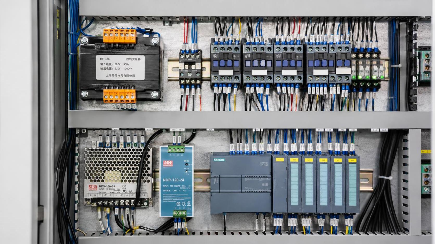
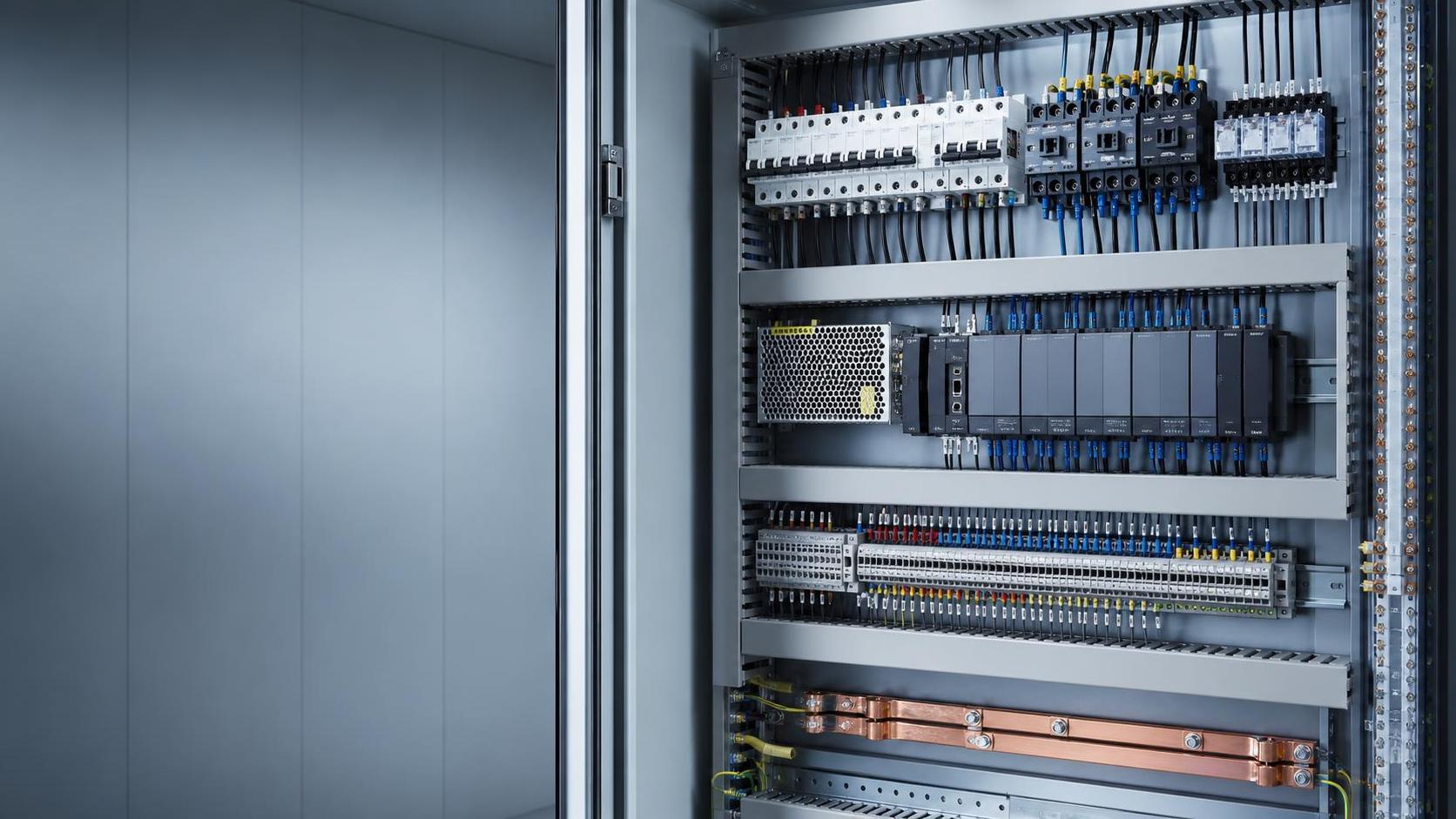
One of the most persistent misunderstandings concerns low-voltage switchgear and controlgear assemblies. IEC 61439 addresses the assembly as a verified system, not simply a collection of individually compliant devices. This distinction is critical. The performance of an assembled switchboard depends on its enclosure, busbar system, clearances, internal separation, thermal behavior, short-circuit withstand, wiring, and the way protective devices are integrated.
A procurement specification should therefore identify the required assembly standard and request evidence of design verification for the relevant configuration. A generic certificate for a similar panel is not always enough. Where an assembly departs from a verified reference design, the manufacturer must be able to explain how the applicable verification has been maintained. This is particularly important when panel builders combine products from different sources, alter busbar dimensions, add high-density variable-speed drives, or modify internal compartmentation.
Routine verification remains equally important. It confirms that the delivered assembly corresponds to the verified design and is free from manufacturing defects. The exact evidence will depend on the project and applicable standard, but technical teams should expect records covering wiring, protective-conductor continuity, insulation properties, mechanical operation, and the declared configuration.

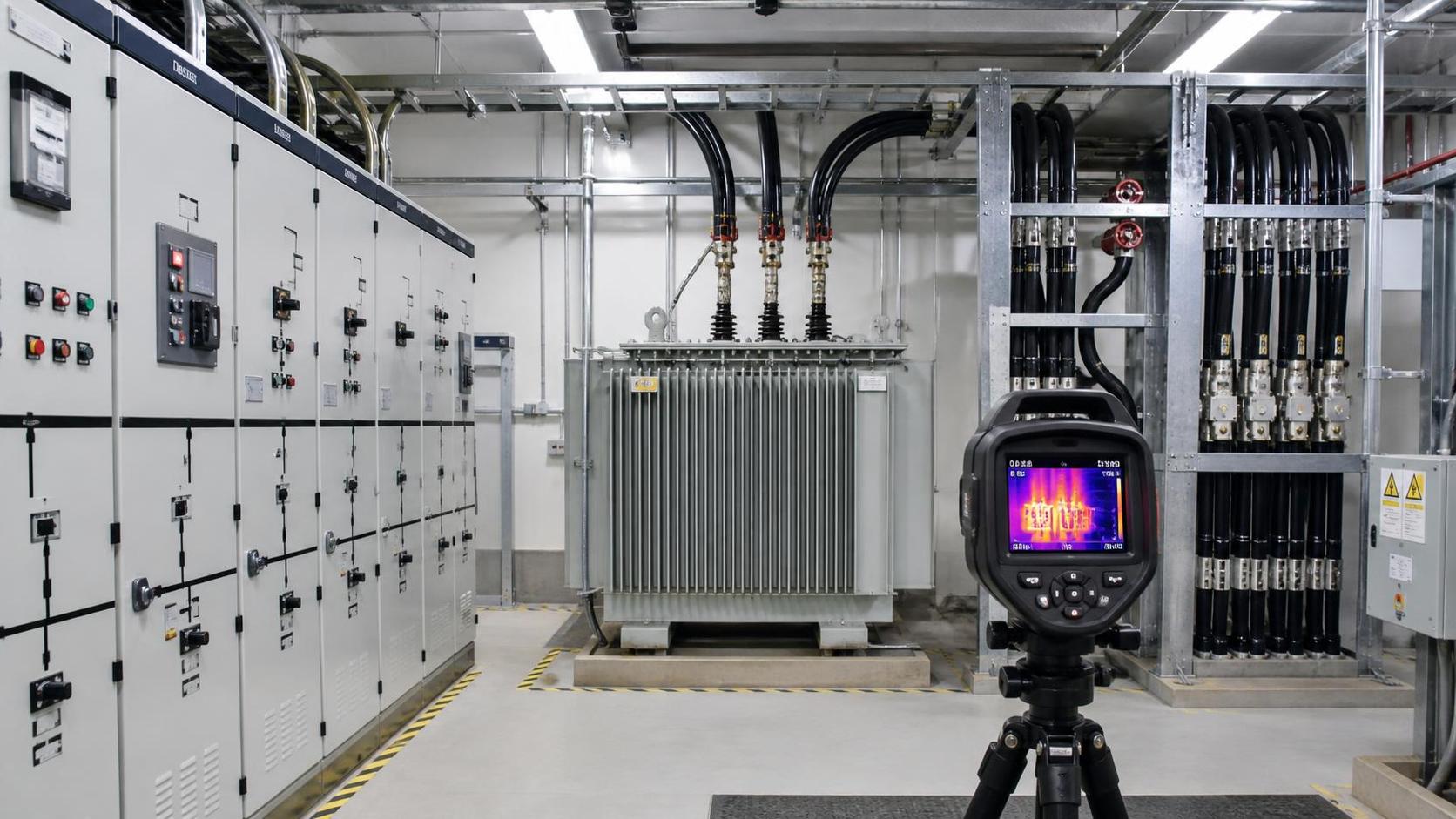
IEC 62271 plays a comparable role for high-voltage switchgear and controlgear, while IEC 60076 is commonly relevant to power transformers. The key evaluation principle is the same: product-level conformity and system-level suitability must be examined separately. A correctly rated transformer can still be paired with inadequate protection, insufficient cooling margin, or an unsuitable tap-changing strategy.
Ratings must match the actual fault and thermal duty
Nominal current and voltage are only the beginning of electrical equipment selection. Evaluators need to test whether the declared ratings correspond to the conditions at the point of installation. For low-voltage assemblies, this includes the rated short-time withstand current, peak withstand current, conditional short-circuit current where applicable, and the coordination of upstream protective devices. For circuit breakers and fuses, breaking capacity, making capacity, utilization category, and selectivity behavior should be assessed in the context of the network, not reviewed as isolated catalogue values.
Thermal performance is similarly easy to underestimate. Equipment installed in an air-conditioned test environment may behave differently in a compact electrical room beside process equipment, in a high-ambient outdoor enclosure, or at elevated altitude. Derating may be necessary for temperature, grouping, ventilation constraints, altitude, or harmonic current. Claims of spare capacity should be tested against these conditions. A board that appears to have 20 percent current reserve on paper may have much less usable margin once enclosure temperature and future non-linear loads are considered.
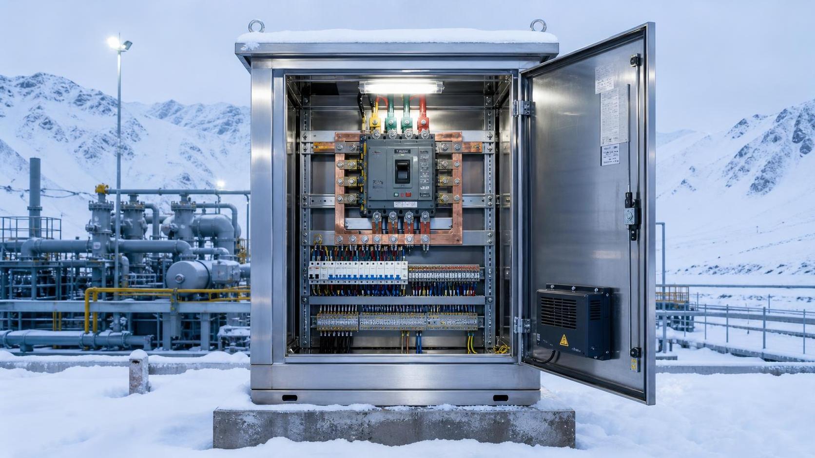
Ingress protection is another area where shorthand can obscure risk. IEC 60529 IP ratings describe protection against access, solid objects, and water under stated test conditions. They do not by themselves establish resistance to corrosion, condensation, chemical exposure, ultraviolet degradation, arc hazards, or pressure washing practices. An outdoor or washdown-area installation needs a broader environmental review than an IP code alone can provide.
Protection coordination cannot be delegated blindly
Protection coordination is the point at which safety, equipment protection, and operational continuity meet. A robust scheme must clear faults quickly enough to protect people and equipment while limiting the loss of supply to the smallest practicable section of the network. This usually requires a coordinated study rather than reliance on default relay or breaker settings.
At a minimum, the evaluator should request time-current curves, protection settings, short-circuit study outputs, and a clear statement of the assumptions used. In more complex systems, load-flow, motor-starting, arc-flash, harmonic, and transient studies may also be needed. The required scope depends on voltage level, network complexity, and consequence of interruption, but the underlying purpose is consistent: verify that protection decisions are defensible.
Selective coordination is often described as an absolute goal. In practice, full selectivity may not be technically achievable across every prospective fault level or may be disproportionate for non-critical feeders. The relevant decision is not whether every circuit has a generic “selective” label. It is whether selectivity has been defined for critical operating scenarios, its limits are documented, and the resulting outage consequence is acceptable to the facility owner.
Digital protection and automation introduce another layer. IEC 60255 is relevant to protection relays, while IEC 61850 is widely used for substation automation and communication architectures. These standards support interoperability, but interoperability should not be assumed merely because devices support the same protocol. Data models, engineering files, time synchronization, cybersecurity controls, fail-safe behavior, and commissioning responsibilities must be verified at the system level.
Conformity assessment needs traceable evidence
Technical evaluators should distinguish among a manufacturer declaration, third-party certification, type-test evidence, routine-test records, and independent inspection. Each can be useful, but they answer different questions. A declaration may establish the supplier's stated responsibility. Third-party certification may provide additional confidence in a defined product range. Test reports can support a specific performance claim. None of these automatically proves that the delivered project equipment is correctly configured, installed, or commissioned.
A practical document register should link each major asset to the evidence required for acceptance. It should identify the applicable standard edition, rated values, drawings, test records, certificates where required, installation instructions, protective-device settings, software or relay configuration, and deviation approvals. Version control matters. A report prepared for an earlier product revision or an obsolete standard edition may not support the final delivered configuration.
Be careful with broad statements such as “CE and IEC certified.” CE marking is a legal conformity marking used within the European Economic Area under applicable legislation; it is not interchangeable with IEC conformity. IEC publishes international standards, while certification is normally administered through relevant certification bodies or schemes. The exact compliance route depends on product category, destination market, and local law. Procurement documents should use precise language rather than combining these concepts as a single generic requirement.
Factory and site testing should answer different questions
Factory acceptance testing is valuable because it exposes manufacturing errors before equipment reaches site, when corrective work is generally less disruptive. Yet a FAT cannot replicate every site condition. It should be built around the project’s highest risks: functional operation of interlocks, protection logic, metering, communication interfaces, alarms, mimic diagrams, auxiliary supplies, and the agreed documentation package.
Site acceptance testing and commissioning then verify the installation in its real network context. This may include cable testing, earthing checks, phase rotation, insulation resistance, functional trip tests, relay injection testing, intertrip checks, synchronization logic, SCADA point-to-point verification, and operational switching procedures. The depth of testing should be proportionate to risk, but “energized successfully” is not an adequate commissioning criterion for critical infrastructure.
Witness points deserve particular attention. If a buyer needs to witness a protection test, inspect internal construction, or approve a non-conformance disposition, the contract should define that point before manufacturing begins. Late witness requirements can delay delivery and create avoidable disagreement about whether a test must be repeated.
Design for change, maintenance, and evidence retention
IEC compliance is not fixed at energization. Settings are changed, feeders are added, transformers are replaced, and operating modes evolve. Any such change can alter fault levels, protection coordination, thermal loading, or the validity of previous assumptions. Facilities with weak change control often retain compliant equipment while gradually losing a demonstrably compliant system.
The handover package should be usable by operations and maintenance teams, not merely complete enough to close a project file. Updated single-line diagrams, as-built layouts, protection settings, test results, spare-parts information, maintenance instructions, and clear equipment identification are operational controls. Where digital models or asset-management systems are used, the final information should be reconciled with the physical installation.
For organizations evaluating power infrastructure solutions under IEC requirements, the strongest decision framework is therefore evidence-led: define the duty, map the applicable standards and local obligations, verify assemblies and protection as installed, witness critical tests, and preserve the records needed to reassess the system after change. Compliance becomes meaningful when it can be demonstrated at the system boundary, under the operating conditions the facility will actually face.
Technical Specifications
- Air Handling Unit Supplier Checklist: Performance Data, Lead Times, and SupportAuthor :Environmental Engineering Director
- Buying Fiberglass Water Tanks Wholesale: Compare Quotes and Delivery CostsAuthor :Environmental Engineering Director
- Choosing an XLPE Power Cable Supplier: Test Reports, Traceability, and Lead TimesAuthor :Grid Infrastructure Analyst
Expert Insights

Chief Security Architect
Dr. Thorne specializes in the intersection of structural engineering and digital resilience. He has advised three G7 governments on industrial infrastructure security.
Related Analysis
- Oct 19, 2026Air Handling Unit Supplier Checklist: Performance Data, Lead Times, and SupportAuthor :Environmental Engineering Director
- Oct 18, 2026Buying Fiberglass Water Tanks Wholesale: Compare Quotes and Delivery CostsAuthor :Environmental Engineering Director
- Oct 17, 2026Choosing an XLPE Power Cable Supplier: Test Reports, Traceability, and Lead TimesAuthor :Grid Infrastructure Analyst
Core Sector // 01
Security & Safety
- Choosing a Step-Down Transformer Supplier: Test Reports, Lead Times, and WarrantyAuthor :Grid Infrastructure Analyst

- Metallurgy Processes That Improve Conductivity and Reliability in Power Grid ComponentsAuthor :Grid Infrastructure Analyst

- How to Size a UPS for Server Rooms: Load, Runtime, and Redundancy FactorsAuthor :Grid Infrastructure Analyst

- How to Choose a Step-Down Transformer for a Control Panel: Key Sizing FactorsAuthor :Grid Infrastructure Analyst

- How Often Should Overseas Power Systems Undergo Safety Inspections?Author :Grid Infrastructure Analyst

- How to Choose Panels for Extreme-Cold Industrial Sites?Author :Grid Infrastructure Analyst

- What Should a Cross-Border EPC Equipment Procurement Reference Include?Author :Grid Infrastructure Analyst

- How to Compare Low-Voltage Equipment for Panel IntegrationAuthor :Grid Infrastructure Analyst