How to Size a UPS for Server Rooms: Load, Runtime, and Redundancy Factors
Author
Date Published
Reading Time
Sizing an uninterruptible power supply UPS for a server room is not a matter of selecting the next kVA rating above a nameplate total. That shortcut is responsible for many awkward outcomes: a UPS that runs close to overload during a normal peak, batteries that cannot bridge the actual transfer window, or an expensive redundant system that still contains a single point of failure.
A defensible UPS specification starts with a practical question: what must remain online, for how long, and through which failures? In a server room, the answer may include servers, storage, switches, firewalls, monitoring appliances, and sometimes limited cooling or control equipment. It rarely means “everything plugged into the room.” The distinction matters because UPS capacity, battery autonomy, bypass architecture, generator behavior, maintenance strategy, and budget all follow from it.
For facility teams and EPC evaluators, the most reliable approach is to calculate the present critical load, test its operating profile against the proposed UPS, then make deliberate decisions about future growth and redundancy. The result should be a power design that can be reviewed by operations, electrical engineers, and procurement without relying on optimistic assumptions.
Start with the load that is actually critical
The inventory should be built from measured load data whenever possible. Equipment labels are useful for identifying circuit requirements, but their maximum input ratings often overstate normal consumption. A server power supply rated at 1,200 W does not necessarily draw 1,200 W in service. Conversely, a room with highly virtualized hosts may have a stable average load but sharp increases during boot sequences, storage activity, or workload migration.
A sensible load schedule separates equipment into three groups: critical IT load, supporting load that must survive a short interruption, and non-critical load. Servers, storage arrays, core network switches, routers, firewalls, and management consoles commonly belong in the first group. Security systems, environmental monitoring, or selected communications equipment may belong in the second. Desk equipment, test benches, printers, comfort cooling, and convenience outlets should not automatically be placed on the UPS just because they are nearby.
Where a live measurement is available, record real power in kW as well as apparent power in kVA, ideally over a representative period. A single reading taken during quiet hours can hide a meaningful peak. For new rooms, use manufacturer input data conservatively and flag which values are estimates. The calculation should remain traceable; otherwise, later changes in rack density become difficult to assess.
kW and kVA are not interchangeable
UPS selection involves both real power, expressed in kW, and apparent power, expressed in kVA. The relationship is governed by power factor:
kW = kVA × power factor
Modern IT power supplies often operate with a relatively high input power factor, but the correct value for a project should come from metering or equipment documentation, not a blanket assumption. The UPS itself also has its own kW-to-kVA capability. A unit may be described by a kVA figure yet have a lower kW rating. If the proposed UPS can supply enough apparent power but not enough real power, it is still undersized.
This is especially relevant where the load mix includes legacy equipment, transformers, motor-driven auxiliaries, or non-linear loads. Harmonic current, crest factor, inrush current, and output waveform compatibility can affect the selection. Server rooms are generally more predictable than industrial process areas, but they are not electrically identical to a simple resistive load bank.
As a working example, assume the verified critical load is 36 kW and 40 kVA. A UPS should be assessed against both values after allowance for growth and redundancy. Selecting a 40 kVA system simply because the present reading is 40 kVA leaves no operational margin. The more useful question is whether the system can support the expected peak load, battery discharge conditions, future rack additions, and any fault scenario that the room’s uptime target requires.
Leave capacity for growth, but do not use growth as an excuse for vague sizing
A capacity allowance is necessary because server rooms rarely stay static. A new storage platform, higher-density compute hardware, additional network ports, or an edge workload can consume the apparent spare capacity quickly. Yet “add 50 percent just in case” is not a design strategy. It can result in oversized equipment operating at a low load fraction, higher initial cost, more floor-space demand, and a battery system that is larger than the actual risk warrants.
A better method is to document growth in layers. Identify committed additions already included in the IT roadmap, likely additions within the intended UPS service period, and speculative demand that can be accommodated through modular expansion or a second power path. Modular UPS designs can be useful when future demand is uncertain, provided that module ratings, frame limits, internal bypass capacity, and maintenance behavior are reviewed carefully.
In practice, the most important margin is not a universal percentage. It is the difference between expected maximum demand and the allowable load under the chosen resilience model. A room operating one small UPS at 85 percent may be acceptable in a limited application. The same loading level can be unacceptable in an N+1 configuration if a failed module or UPS forces the remaining capacity beyond its supported limit.
Runtime should support an operating sequence, not an arbitrary number of minutes
Battery runtime is often the most misunderstood part of an uninterruptible power supply UPS decision. The UPS battery does not necessarily need to carry the server room through a prolonged utility failure. In many facilities, its primary job is to maintain clean output while a generator starts, stabilizes, and accepts the load. In a room without standby generation, the objective may instead be controlled shutdown, protection of data integrity, or continuity until the utility supply is restored.
That means runtime must be tied to a written operating sequence. Consider the utility-failure detection time, generator start and transfer sequence where applicable, the time required for IT systems to shut down cleanly if generation does not start, and a realistic allowance for degraded battery performance. Battery autonomy also changes with load. Runtime charts supplied by manufacturers should be read at the expected kW load, not at the nominal UPS rating.
Environmental conditions matter more than many procurement documents acknowledge. Battery life and available capacity are influenced by temperature, age, charging conditions, maintenance history, and battery technology. A runtime calculation based on a new battery string in a controlled test condition should not be treated as a permanent field result. Specify the required end-of-life runtime and establish how it will be verified during maintenance.
Cooling deserves a separate conversation. The UPS may keep IT equipment energized while the cooling system is offline, but that does not mean the room can safely operate for the full battery duration. For short transitions this may be manageable; for longer outages, heat accumulation, room volume, rack density, and available ventilation need engineering review. It is usually more practical to coordinate critical cooling with the generator-backed electrical design than to place large air-conditioning loads on the same battery-backed UPS without a detailed analysis.
Choose redundancy based on the failure you intend to tolerate
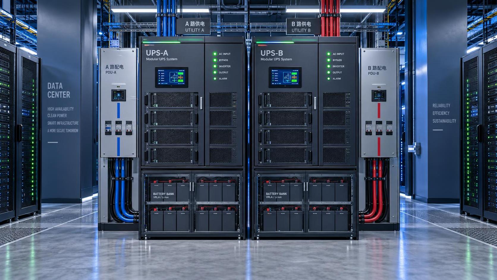
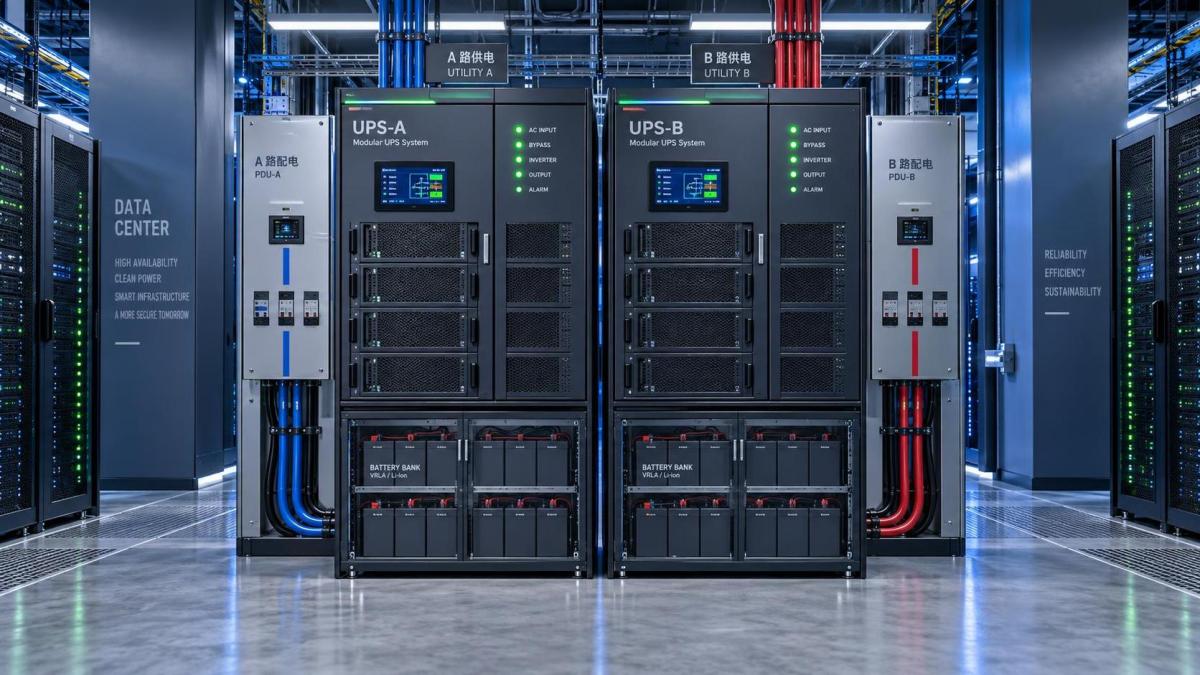
Redundancy terminology is useful only when it is tied to the actual architecture. An N system provides the capacity required for the critical load. N+1 adds one additional module or unit so that the required load can still be served after one planned or unplanned component loss, assuming the design supports that failure mode. A 2N arrangement provides two independent paths, each capable of carrying the full critical load. These are materially different investments and should not be treated as interchangeable labels.
An N+1 modular UPS can provide good resilience against a module failure, but it does not automatically eliminate risk from a common input, shared battery arrangement, common output distribution, maintenance bypass, or downstream power distribution unit. Likewise, two UPS units do not create meaningful 2N protection if both feed a single-corded server or join before a common breaker. The power path must be traced all the way to the load.
For dual-corded IT equipment, the strongest practical arrangement often distributes the A and B feeds through separate paths, with each path sized to carry the intended duty during a failure. Single-corded devices require additional thought: a properly selected static transfer switch may be appropriate, but it introduces its own compatibility and maintenance considerations. Network devices, management appliances, and smaller legacy systems are frequently where an otherwise redundant design becomes compromised.
Do not overlook bypass, distribution, and upstream coordination
A UPS is part of a power chain, not an isolated cabinet. The upstream feeder, protective devices, earthing arrangement, generator, automatic transfer equipment, external maintenance bypass, output panels, rack PDUs, and monitoring system all influence real availability. A good UPS can still be defeated by poorly coordinated protective devices or by an external bypass arrangement that cannot be operated safely during maintenance.
Static bypass capability needs particular attention. When a UPS transfers to bypass because of overload or internal fault, the bypass source and downstream protection must be capable of carrying the condition long enough for the protective scheme to act as intended. This must be reviewed against the manufacturer’s data, the electrical single-line diagram, and the project’s fault-level study where one is required. It is not a detail to leave until commissioning.
Compliance requirements should be confirmed for the installation location and project scope. Relevant expectations may involve electrical safety, product conformity, battery-room requirements, fire protection, access, ventilation, and local inspection rules. CE, UL, ISO references may be relevant in different procurement or management contexts, but none should be treated as a substitute for verifying the specific equipment listing, installation standard, and authority requirements applicable to the site.
A practical review before issuing the UPS specification
Before selecting a model, bring the calculation into one short design review. Confirm the measured and forecast critical loads in kW and kVA. State the required runtime at the anticipated load and at battery end of life. Identify whether the resilience target is N, N+1, or separate A/B paths. Then test what happens during a module failure, a UPS failure, a battery maintenance event, generator non-start, overload transfer, and planned bypass operation.
This review often exposes the uncomfortable but valuable questions. Can one remaining path carry the full load? Are single-corded devices identified? Does the generator accept the UPS input profile? Is there enough physical space and structural provision for battery replacement? Who receives alarms after hours, and can operators distinguish a battery warning from a true loss-of-redundancy event?
For industrial facilities, these decisions should be documented alongside the electrical single-line diagram, rack load schedule, battery assumptions, and maintenance procedure. That level of discipline is more useful than choosing the largest available rating. The right UPS is the one whose capacity, autonomy, and fault tolerance match the room’s real operating plan—and whose limitations are known before the first utility disturbance tests them.
Technical Specifications
- How to Select Electronic Hotel Key Card Locks for Guest Rooms and Staff AreasAuthor :Safety Compliance Lead
- How to Select Lab Instruments for Reliable Chemical Analysis WorkflowsAuthor :Precision Metrology Expert
- How to Size a UPS for Server Rooms: Load, Runtime, and Redundancy FactorsAuthor :Grid Infrastructure Analyst
Expert Insights

Chief Security Architect
Dr. Thorne specializes in the intersection of structural engineering and digital resilience. He has advised three G7 governments on industrial infrastructure security.
Related Analysis
- Sep 17, 2026How to Select Electronic Hotel Key Card Locks for Guest Rooms and Staff AreasAuthor :Safety Compliance Lead
- Sep 16, 2026How to Select Lab Instruments for Reliable Chemical Analysis WorkflowsAuthor :Precision Metrology Expert
- Sep 15, 2026How to Size a UPS for Server Rooms: Load, Runtime, and Redundancy FactorsAuthor :Grid Infrastructure Analyst
Core Sector // 01
Security & Safety
- How to Size a UPS for Server Rooms: Load, Runtime, and Redundancy FactorsAuthor :Grid Infrastructure Analyst

- How to Choose a Step-Down Transformer for a Control Panel: Key Sizing FactorsAuthor :Grid Infrastructure Analyst

- How Often Should Overseas Power Systems Undergo Safety Inspections?Author :Grid Infrastructure Analyst

- How to Choose Panels for Extreme-Cold Industrial Sites?Author :Grid Infrastructure Analyst

- What Should a Cross-Border EPC Equipment Procurement Reference Include?Author :Grid Infrastructure Analyst

- How to Compare Low-Voltage Equipment for Panel IntegrationAuthor :Grid Infrastructure Analyst

- IEC-Compliant Power Infrastructure: Key Design and Verification RequirementsAuthor :Grid Infrastructure Analyst

- Updated EN 61000-6-4:2026 Raises EMC Compliance Bar for EU-Bound Industrial EquipmentAuthor :Grid Infrastructure Analyst