How to Choose a Step-Down Transformer for a Control Panel: Key Sizing Factors
Author
Date Published
Reading Time
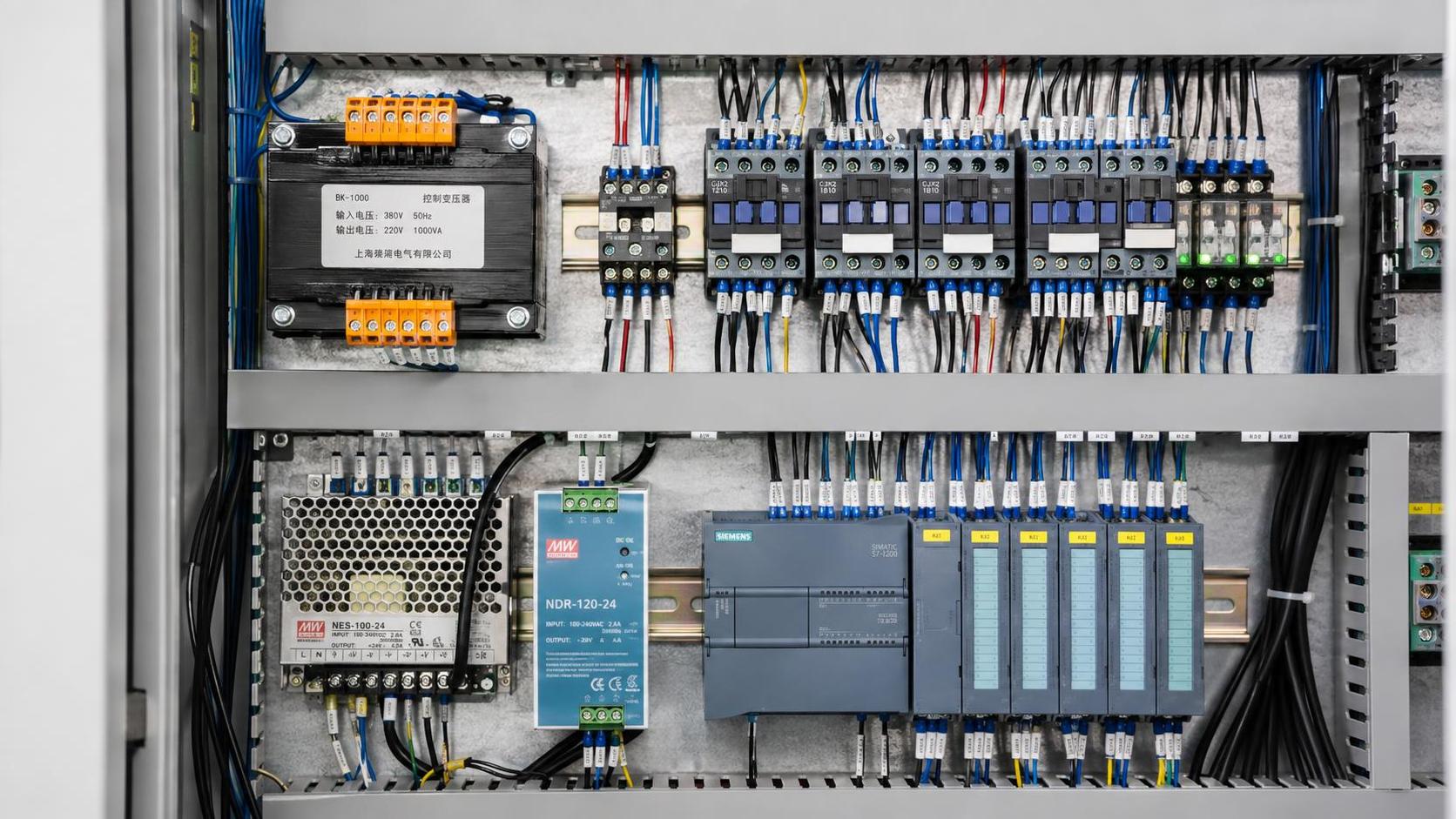
A control panel may operate normally during bench testing and still develop nuisance trips, low control voltage, overheated transformers, or contactors that chatter once the full machine sequence begins. The transformer is often blamed only after the symptoms appear, but the underlying issue is usually earlier in the selection process: its voltage ratio was correct, while its real load duty was not.
To choose a step down transformer for control panel use, start with the required secondary voltage and then size the unit for the maximum simultaneous demand, including coil inrush, power-supply input current, pilot devices, and future additions. The selected VA rating must also suit the supply frequency, installation temperature, enclosure conditions, insulation system, protection method, and applicable safety requirements. A transformer that merely matches nominal voltage is not necessarily large enough, thermally suitable, or electrically appropriate for the panel.
Start with the voltage system, not the transformer nameplate
Control transformers reduce an available line voltage to the voltage required by the control circuit. Typical arrangements include stepping 480 V, 400 V, 380 V, 240 V, or 208 V down to 120 V, 110 V, 24 V, or another control voltage. Before calculating VA, confirm the actual supply conditions at the panel terminals rather than relying only on a project description or a previous panel design.
Three details deserve early attention:
- Primary voltage and phase connection: Verify whether the transformer primary will be connected line-to-line or line-to-neutral, and whether the available system is single-phase or three-phase. Many control transformers use a single-phase primary even inside a three-phase motor control panel.
- Frequency: A transformer designed for 60 Hz may not be suitable at its full voltage rating on a 50 Hz supply. Lower frequency increases core flux and can cause excessive magnetizing current and overheating unless the manufacturer permits the intended combination.
- Secondary tolerance: The circuit needs an acceptable operating voltage range, not simply a nominal value. A 24 V AC coil, relay, indicator, or control power supply may behave differently when the incoming mains is low and several loads are energized.
Multi-tap primaries are useful where the facility supply may vary between common nominal voltages. They are not a substitute for confirming the supply. Connecting the wrong primary taps can overvoltage the secondary, reduce it below the operating threshold, or overstress the transformer winding.
The practical sizing question: what is energized at the same time?
Nameplate VA is the transformer’s apparent-power capacity. It should be compared against the credible simultaneous burden of the secondary circuit, not the total of every device listed on the bill of materials. A panel may contain numerous relays and contactors that cannot all be energized in the same operating state. Conversely, a smaller circuit may have a severe momentary load if multiple contactor coils pick up together.
Build the load estimate from the actual control schematic and sequence of operation. Include every device fed from the transformer secondary during the highest-demand condition:
- Contactor, starter, interposing relay, solenoid, and valve coils
- Timers, annunciators, pilot lights, audible alarms, and interface relays
- PLC power supplies, remote I/O supplies, HMI power supplies, and communication equipment where fed from the same control transformer
- Safety relays, safety controllers, light curtain interfaces, and other protective control devices
- Electronic modules with DC power supplies that draw AC input current from the transformer
For each item, distinguish between sealed VA and inrush VA. Sealed VA is the continuing burden after an electromagnetic coil has closed or stabilized. Inrush VA is the higher demand during pull-in. A contactor coil may need substantially more VA for a short period than it requires while held energized. If the transformer cannot support this pull-in demand without an excessive voltage dip, the contactor may fail to close cleanly, release prematurely, or chatter.
The same issue applies to several loads starting together. A sequence that energizes one coil at a time may work with a lower-capacity transformer than a circuit where a safety reset, hydraulic valve bank, and motor contactors are all commanded simultaneously. Read the timing logic, not just the device count.
A useful way to separate continuous and momentary demand
Calculate the steady-state burden first by adding the sealed VA of loads that remain energized together. Then identify the largest credible inrush event. The transformer must have sufficient regulation and short-duration capacity for that event while carrying the ongoing load. Manufacturer data is important here because transformer inrush capability, secondary voltage regulation, and coil burden characteristics affect the result.
A simplified review may use the following logic:
- Map each operating mode: idle, start, normal run, alarm, shutdown, and maintenance where applicable.
- For each mode, list devices energized continuously from the secondary.
- Identify which inductive coils can pull in simultaneously and obtain their inrush VA data.
- Check whether electronic power supplies have startup surge, power-factor effects, or a manufacturer-stated upstream transformer requirement.
- Select a VA rating that supports the governing condition with a reasonable engineering margin for tolerance and planned additions.
Do not assume a DC coil eliminates the inrush question. The coil itself may be supplied by a DC power supply, but the AC input side of that supply can impose a charging surge when energized. Power supply documentation normally provides the relevant input characteristics or recommended protection arrangement.
Why a simple VA total can still produce a poor selection
Adding published VA values is necessary, but it does not always predict field behavior. Transformer output voltage changes with load, and the amount of change depends on transformer regulation. A secondary rated at a nominal voltage under specified conditions can drop when a large inrush burden occurs. If the circuit operates close to the minimum pickup voltage of a contactor or relay, that dip can become operationally significant.
Consider a panel with a control transformer feeding a PLC power supply and several AC contactor coils. The PLC supply may tolerate a brief disturbance, while a coil at the end of a long control wiring run may see a lower voltage because of both transformer sag and conductor voltage drop. The result can be intermittent behavior that looks like a wiring fault. It may only occur during a particular sequence, after the enclosure has warmed up, or when the plant supply is already near its lower tolerance.
Electronic loads need special treatment. Switched-mode power supplies do not always present a linear VA burden. Their rectifier-capacitor input stages can draw current in pulses, especially during energization. A conventional control transformer may be appropriate, but the selection should be checked against the power-supply manufacturer’s input current, inrush information, and recommended upstream protection. Avoid converting watts directly to transformer VA without considering power factor and input current specifications.
Choose a secondary voltage that matches the control architecture
Control voltage decisions often arise before transformer sizing, but they should be reviewed together. A 24 V AC secondary may be suitable for conventional AC pilot circuits, while 24 V DC architecture usually requires a transformer feeding a correctly sized DC power supply or a separate DC supply arrangement. A 120 V AC circuit can simplify use of certain legacy devices but may demand more attention to touch protection, conductor identification, and enclosure practices. The proper choice depends on the equipment interface requirements and the control philosophy, not on transformer availability alone.
Where sensitive electronics and inductive loads share one secondary, separate branches and protection can improve fault containment. In some designs, a control transformer feeds a protected AC distribution section and a dedicated power supply for DC controls. This can prevent a fault in a pilot device branch from disabling every electronic component, though the protection scheme must be coordinated with transformer capability.
Account for the enclosure as part of the thermal design
A transformer’s VA rating assumes defined operating conditions. Inside a compact enclosure, it is exposed to heat from variable-frequency drives, power supplies, contactors, braking resistors, and external solar loading. High ambient temperature reduces thermal margin. Dust accumulation and restricted airflow can further limit heat dissipation, particularly where the transformer is mounted near the top of a crowded panel.
Review the transformer’s ambient temperature rating and insulation class alongside the panel thermal design. A higher insulation class does not automatically mean the transformer may be used without regard to enclosure temperature; it describes the thermal capability of the insulation system under specified conditions. The relevant question is whether the assembled panel remains within the component’s permitted operating environment.
Installation location also affects noise and mechanical reliability. Control transformers can produce an audible hum that becomes more noticeable when mounted on a thin or poorly supported panel surface. Secure mounting, appropriate hardware, and adequate spacing from heat-sensitive devices reduce avoidable issues. Keep wiring clear of terminals and follow specified torque values, because loose connections can create localized heating that may be misdiagnosed as transformer failure.
Protection and grounding need to be decided with the transformer
Primary and secondary overcurrent protection should be selected in accordance with the transformer instructions, the applicable electrical code, and the panel’s overall fault-protection design. Transformer magnetizing inrush may be high at energization, so a protective device chosen only from normal primary current can trip unnecessarily. At the same time, oversizing protection without checking conductor ampacity and transformer limits can leave the circuit insufficiently protected.
The secondary arrangement matters just as much. Determine whether the control circuit requires a grounded secondary conductor, an ungrounded secondary, or a specific reference arrangement. This decision affects fault detection, fuse placement, troubleshooting practices, and how one fault may propagate through the system. A grounded control circuit can make certain faults easier to identify, while an ungrounded circuit may continue operating after a first ground fault unless monitoring is provided. Neither approach should be selected by habit.
Where a secondary is grounded, establish the grounding point deliberately and avoid unintended multiple bonding points. Multiple references can create confusing fault paths and make diagnostic readings unreliable. The panel documentation should clearly identify the secondary voltage, protective devices, grounding arrangement, and terminal designations.
Compliance is more than a label on the component
Technical evaluation should confirm that the transformer is appropriate for the intended installation jurisdiction and panel construction requirements. Depending on where the equipment will be installed and how it is supplied, this may involve recognized safety approvals, insulation and dielectric requirements, terminal finger-safety provisions, creepage and clearance considerations, marking, and temperature limits. The transformer’s documentation should state its applicable ratings rather than leaving assumptions to the panel builder.
Also check whether a control transformer is intended for industrial control duty rather than general-purpose use. Control-duty units are commonly designed with operating characteristics suited to relay and contactor circuits, including the ability to handle short-duration inrush demands. A general-purpose transformer with the same nominal voltage and VA marking may not deliver equivalent performance in a coil-heavy panel.
When a larger transformer is not the right correction
Increasing VA capacity can solve an undersizing problem, but it should not be used to hide a design fault. If control voltage drops only when a particular coil energizes, inspect the coil rating, cable run, terminal condition, secondary fuse contacts, and transformer tap connection before replacing the unit. A damaged coil or a coil supplied at the wrong voltage can create abnormal current demand. Similarly, repeated protective-device operation may indicate a downstream short circuit rather than inadequate transformer capacity.
A larger transformer can also increase available fault current on the secondary. That may change the required rating or coordination of branch protection. Any upgrade should therefore include a review of secondary conductors, protective devices, terminal blocks, and connected equipment—not just the transformer mounting footprint.
A defensible specification for the review file
The final selection record should identify the primary voltage and tap used, frequency, secondary voltage, continuous calculated burden, governing inrush condition, chosen VA rating, ambient conditions, insulation rating, enclosure location, and primary/secondary protection approach. Include the source of coil and power-supply load data, especially where inrush behavior controls the selection.
This record is useful when a panel is modified later. Adding a few interface relays, a larger solenoid valve, an HMI, or a remote I/O assembly can consume the margin that made the original transformer reliable. A properly documented selection makes it possible to assess those changes before they appear as unexplained low-voltage faults during commissioning.
Technical Specifications
- How to Select Electronic Hotel Key Card Locks for Guest Rooms and Staff AreasAuthor :Safety Compliance Lead
- How to Select Lab Instruments for Reliable Chemical Analysis WorkflowsAuthor :Precision Metrology Expert
- How to Size a UPS for Server Rooms: Load, Runtime, and Redundancy FactorsAuthor :Grid Infrastructure Analyst
Expert Insights

Chief Security Architect
Dr. Thorne specializes in the intersection of structural engineering and digital resilience. He has advised three G7 governments on industrial infrastructure security.
Related Analysis
- Sep 17, 2026How to Select Electronic Hotel Key Card Locks for Guest Rooms and Staff AreasAuthor :Safety Compliance Lead
- Sep 16, 2026How to Select Lab Instruments for Reliable Chemical Analysis WorkflowsAuthor :Precision Metrology Expert
- Sep 15, 2026How to Size a UPS for Server Rooms: Load, Runtime, and Redundancy FactorsAuthor :Grid Infrastructure Analyst
Core Sector // 01
Security & Safety
- How to Size a UPS for Server Rooms: Load, Runtime, and Redundancy FactorsAuthor :Grid Infrastructure Analyst

- How to Choose a Step-Down Transformer for a Control Panel: Key Sizing FactorsAuthor :Grid Infrastructure Analyst

- How Often Should Overseas Power Systems Undergo Safety Inspections?Author :Grid Infrastructure Analyst

- How to Choose Panels for Extreme-Cold Industrial Sites?Author :Grid Infrastructure Analyst

- What Should a Cross-Border EPC Equipment Procurement Reference Include?Author :Grid Infrastructure Analyst

- How to Compare Low-Voltage Equipment for Panel IntegrationAuthor :Grid Infrastructure Analyst

- IEC-Compliant Power Infrastructure: Key Design and Verification RequirementsAuthor :Grid Infrastructure Analyst

- Updated EN 61000-6-4:2026 Raises EMC Compliance Bar for EU-Bound Industrial EquipmentAuthor :Grid Infrastructure Analyst