Choosing Floor Standing Metal Enclosures: Size, IP Rating and Cooling
Author
Date Published
Reading Time
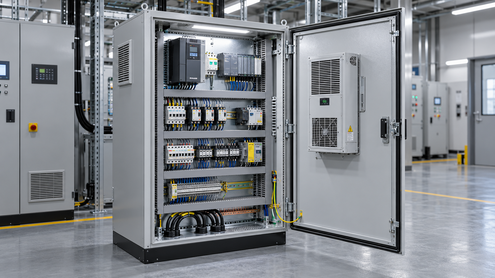
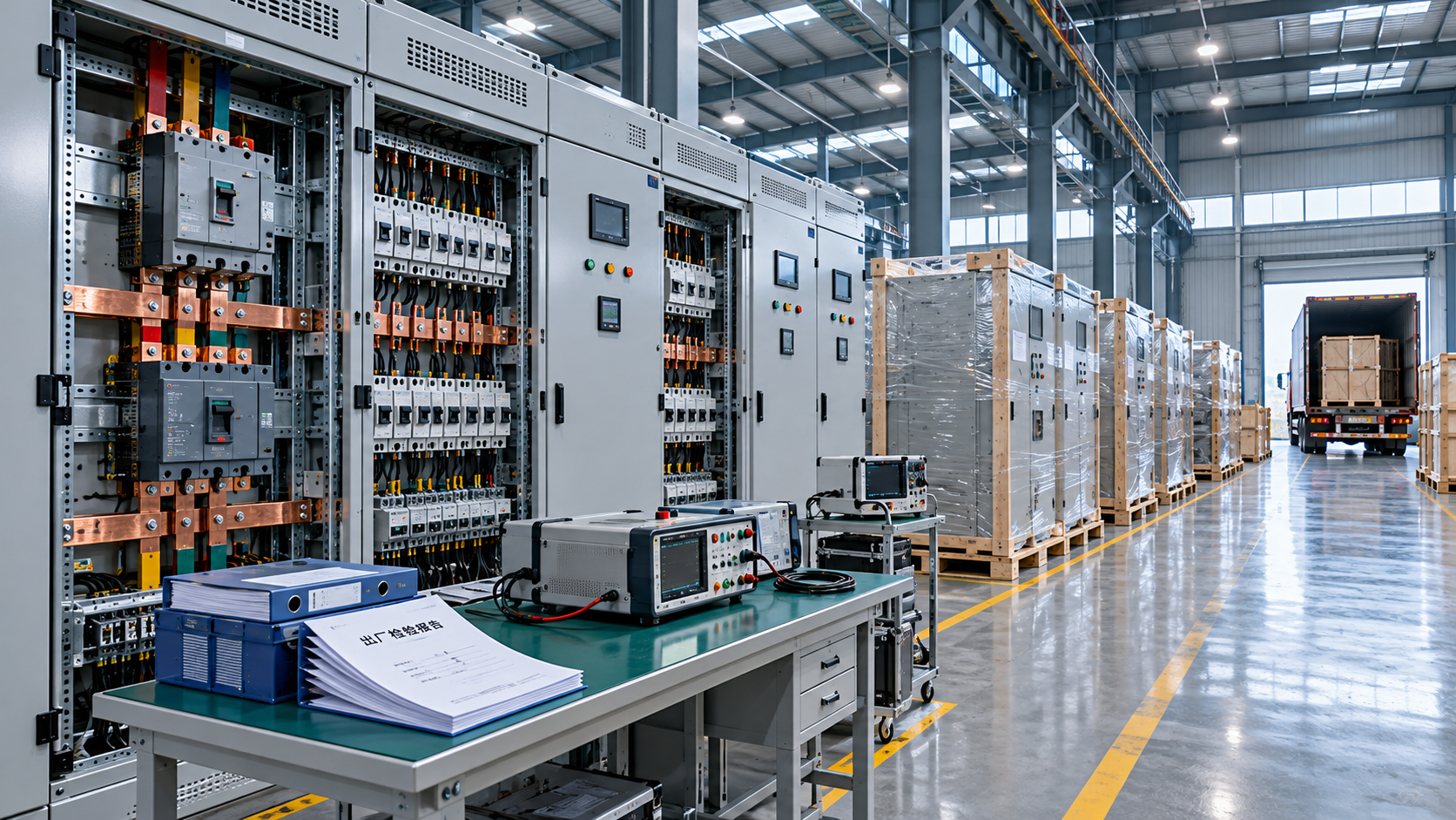
Choose floor standing metal enclosures by starting with the equipment layout and heat load, then verifying that the complete enclosure—including cable entries and cooling equipment—provides the protection required at the installation site. A cabinet that fits the available floor space can still be unsuitable if cable bends obstruct the door, components exceed their temperature limits, or a ventilation opening compromises the specified IP rating.
In a crowded control room, for example, the immediate concern may be fitting an enclosure between adjacent equipment. The more consequential question is whether it can also be wired, cooled and maintained in that position. Establish those requirements before comparing external dimensions or ordering accessories.
Size the usable interior, not just the footprint
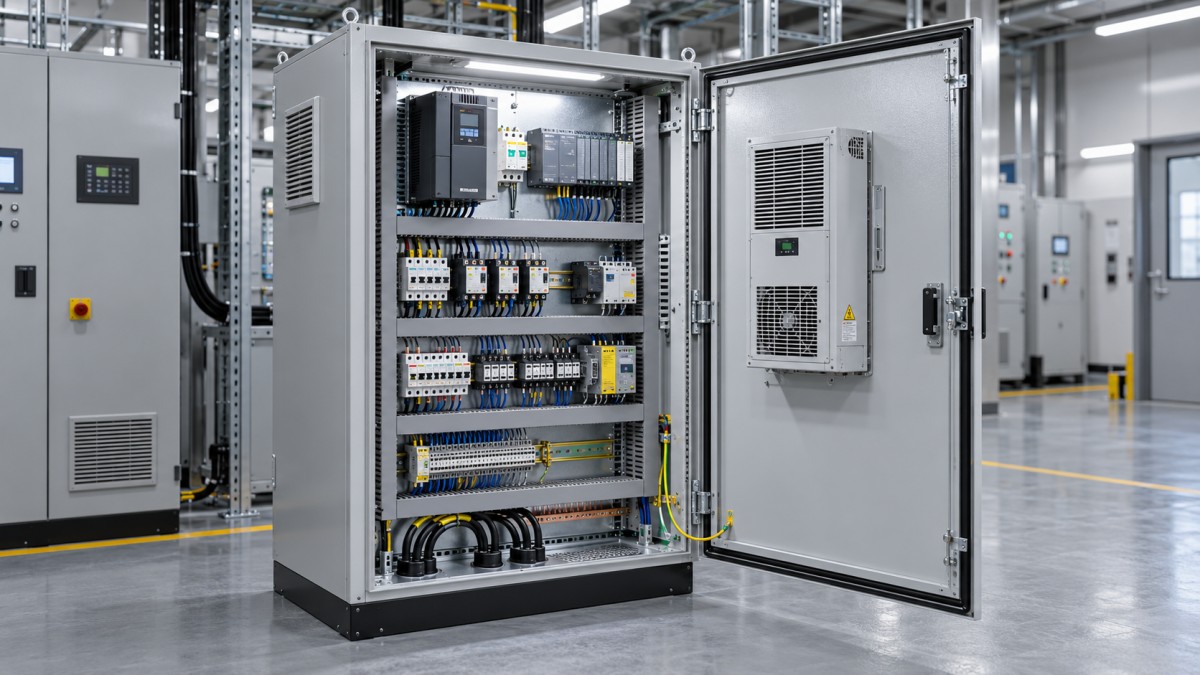
Begin with a scaled layout of the mounting plate, doors, side panels and any internal partitions. Include drives, power supplies, terminals, protective devices and control equipment, together with wire ducts, cable supports and protective bonding connections. Use the actual dimensions of proposed components rather than assuming that the nominal cabinet width is available for mounting.
Check three dimensions separately:
- Height: Allow space above and below heat-producing equipment for the clearances specified by its manufacturer. Reserve accessible routes for cables entering from the top or bottom.
- Width: Account for wire ducts, terminal access and separation between power and signal wiring. Check whether door-mounted devices or side-mounted equipment intrude into the usable width.
- Depth: Include component projections, connector and cable bend space, door-mounted equipment and any clearance needed between live parts and enclosure surfaces.
A cabinet can look adequately sized in a front-view drawing but fail the depth check once door-mounted controls are included. Similarly, a wide mounting plate may not be fully usable if frame members, hinges or gland plates obstruct cable routes. Verify internal dimensions on the supplier’s drawings and request the usable mounting dimensions where they are not shown.
Leave room for installation and service
Equipment must be fitted and replaced, not merely accommodated in its operating position. Check that doors can open sufficiently, mounting plates can be installed, and heavy components can be lifted into place. External space is also needed for access to cooling units, filters and cable connections. A line-up of enclosures against a wall may restrict rear or side access even when each cabinet’s dimensions appear acceptable individually.
Reserve capacity for known additions, such as planned terminals or an additional drive, but identify where that capacity will be used. Empty volume alone is not a useful expansion allowance if the remaining space lacks cable access, mounting support or cooling capacity. For a multi-bay assembly, also confirm how adjacent sections connect and whether partitions are required for electrical or thermal reasons.
Match ingress protection to the actual exposure
An IP rating describes protection against access to hazardous parts and ingress of solid objects and water under specified test conditions. The first digit addresses solids and access; the second addresses water. It is not a general measure of corrosion resistance, mechanical strength, electrical safety or suitability for every outdoor environment.
Define the exposure before specifying a rating. A dry electrical room, a dusty production area, an outdoor installation and a washdown zone impose different demands. Record whether dust can accumulate, whether water is present as splashes or jets, and whether cleaning procedures bring water into contact with doors, seams or cable entries. Consider the direction and frequency of exposure as well as the consequences of water reaching energized equipment.
Do not treat a higher water digit as automatic evidence of every lower-rated water condition. Where multiple types of water exposure matter, check the applicable markings and test documentation. Likewise, an IP rating does not establish protection against immersion unless the relevant water-protection level is specified and its conditions are suitable for the application.
The rating applies to a configuration
Ask which enclosure configuration was assessed: doors, locks, seals, gland plates, blanking plugs and fitted accessories can all affect the result. A cabinet body advertised with an IP rating does not guarantee that the assembled installation retains it after holes are cut or third-party components are added.
Cable glands and conduit fittings should suit the cable or conduit used and the required protection. Check the permitted cable diameter, sealing arrangement and installation instructions. Any unused opening needs a suitable closure. When a cooling unit, fan or window is fitted, confirm the rating of the complete interface rather than relying on the individual accessory’s label.
IP and NEMA enclosure designations use different frameworks and should not be assumed interchangeable. Where a specification calls for either designation, obtain documentation against the applicable requirement instead of converting a label by assumption.
Calculate the thermal duty before choosing cooling
Heat removed from the enclosure must cover losses from installed equipment, adjusted for heat entering or leaving through the enclosure surfaces. Start with the loss data supplied for drives, power supplies, transformers, contactors and other heat-producing devices at the intended operating load. Electrical input power is not the same as heat loss; using the full input rating as the dissipated load can produce a misleading result.
Establish the maximum permitted internal temperature from the most temperature-sensitive equipment, not from the cabinet material. Check where each device measures or specifies its ambient temperature: a controller’s local inlet temperature can be higher than the general air temperature inside the enclosure. Also establish the highest expected external ambient temperature, accounting for nearby machinery, restricted airflow and solar exposure where relevant.
The relationship between internal and external temperatures narrows the cooling choices. Passive surface cooling depends on a temperature difference and the effective exposed surface area. Direct ventilation exchanges cabinet air with ambient air, so it cannot normally cool the interior below that ambient temperature. A sealed heat exchanger also relies on a suitable temperature difference between the two air paths. When the required internal temperature is close to or below the external ambient, active refrigeration or another suitable cooling method may be necessary.
Use the cooling equipment supplier’s sizing method with the full application data. Include enclosure dimensions, installation arrangement, heat load, temperature limits and external conditions. Enclosures installed side by side, against a wall or in direct sun can behave differently from a freestanding cabinet with unobstructed surfaces. Preserve the assumptions and calculations so that a later equipment change can be checked against the available cooling capacity.
Compare cooling methods against the environment
- Passive cooling: Suitable when the heat load, exposed surface area and temperature difference allow it. It adds no ventilation opening, but crowded layouts can still create local hot spots.
- Filtered fan ventilation: Useful where ambient air is cool enough and airborne contamination can be managed. Filters require maintenance, and the fan, filter and outlet must provide the required installed protection.
- Air-to-air heat exchanger: Keeps internal and external air streams separate when correctly installed. Performance depends on the temperature difference and available airflow on both sides.
- Enclosure air conditioner: Can provide cooling below external ambient temperature, subject to its specified operating limits. Check heat rejection, condensate drainage, power supply and maintenance access.
- Air-to-water heat exchanger: Can be appropriate where a suitable cooling-water supply is available. Assess water quality, temperature, flow, leak risk and the consequences of an interrupted supply.
Do not select a unit solely on its nominal cooling capacity. Capacity changes with operating conditions, and a unit rejecting heat into a small enclosed room may raise the room temperature that it depends on for cooling. Confirm performance at the specified internal and external design temperatures, including the effect of dirty filters or restricted airflow where applicable.
Control airflow and condensation inside the cabinet
Cooling capacity at the enclosure level does not guarantee that every component receives sufficiently cool air. Arrange heat-producing equipment so that exhaust air from one device is not directed into the inlet of another. Respect the component manufacturer’s mounting orientation and clearance instructions. Where equipment is densely packed, consider internal circulation or ducting, while ensuring that it does not obstruct service or interfere with protective barriers.
Condensation requires a separate assessment. Moist air can condense on surfaces that fall below its dew point, including surfaces cooled by an air conditioner or water-fed heat exchanger. Seals reduce air exchange but do not automatically eliminate moisture introduced during installation, maintenance or temperature cycling. A suitable heater, humidity control, drain arrangement or combination may be needed, depending on the environment and cooling design.
Check where condensate will go during normal operation and under a blocked-drain condition. It should not be directed toward electrical components or create a slip hazard outside the cabinet. For intermittent operation, consider both extremes: overheating when the system is running and moisture formation when it is switched off.
Check material, construction and electrical integration
Painted steel and stainless steel are common choices, but the relevant comparison is resistance to the actual environment rather than the material name alone. Review exposure to cleaning chemicals, moisture, salt, abrasion and dissimilar metals. Specify the required finish or material grade where the application demands it, and check the compatibility of hinges, fasteners and seals as well as the enclosure panels.
Mechanical construction matters during transport and installation. Confirm the enclosure’s permitted loading, lifting method, floor fixing and requirements for supporting heavy components. A plinth may improve cable access or help with housekeeping, but it also changes the overall height and can affect anchoring or the intended protection at the base.
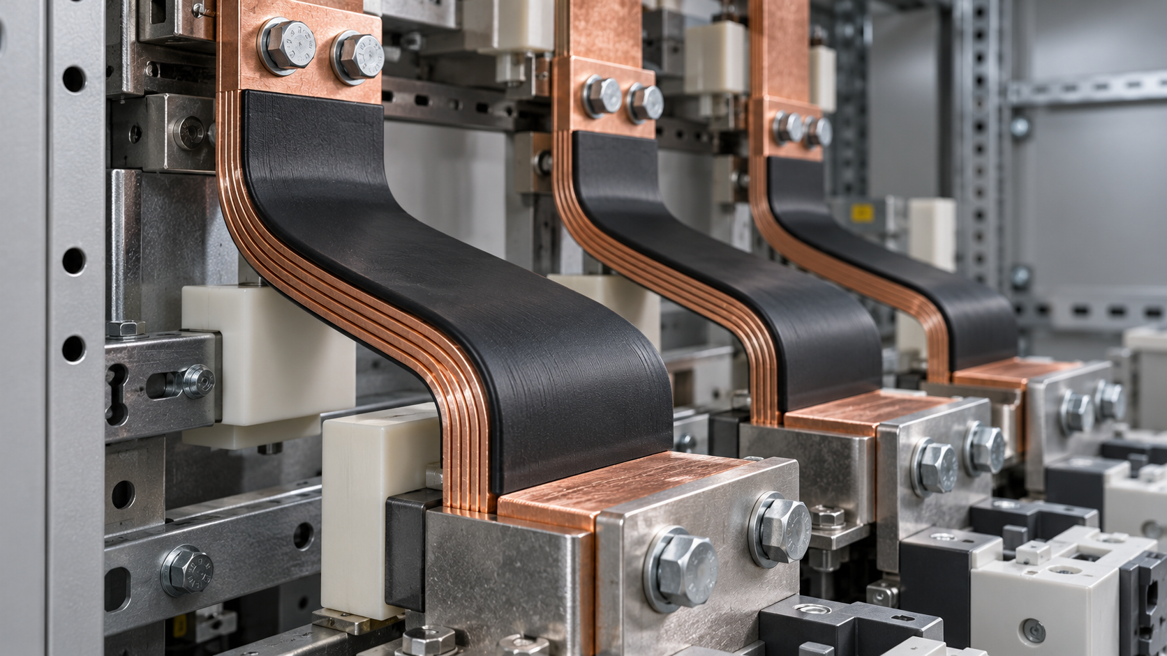
Electrical integration should be reviewed with the assembly design. Confirm provisions for protective bonding of doors, removable panels and mounting plates, along with cable-entry arrangements and any required separation or barriers. The enclosure rating alone does not establish compliance of the completed electrical assembly; applicable assembly requirements depend on its function and destination.
Use supplier documentation to resolve the final trade-offs
Before releasing a specification, compare the proposed cabinet and accessories against the same operating conditions. Request dimensional drawings, usable mounting space, load limits, material and finish details, ingress-protection documentation and cooling performance data. Identify which modifications will be made after delivery and who is responsible for maintaining the required protection at those interfaces.
Pay particular attention to conflicts between requirements. A smaller enclosure may fit the room but require a larger cooling unit; that unit may then obstruct a walkway or need an air outlet that the room cannot accommodate. A sealed enclosure may suit a dusty area, yet its thermal design must still handle the installed losses. Resolve these interactions on the layout and in the thermal calculation before treating the cabinet as an approved selection.
Technical Specifications
Expert Insights

Chief Security Architect
Dr. Thorne specializes in the intersection of structural engineering and digital resilience. He has advised three G7 governments on industrial infrastructure security.
Related Analysis
- Oct 31, 2026Choosing Floor Standing Metal Enclosures: Size, IP Rating and CoolingAuthor :Grid Infrastructure Analyst
- Oct 30, 2026China and Eurasian Economic Union Hold Sixth Trade Agreement Committee MeetingAuthor :
- Oct 30, 2026Choosing a Lint-Free Wipes Factory: How to Evaluate Quality and CapacityAuthor :Precision Metrology Expert
Core Sector // 01
Security & Safety
- Choosing Floor Standing Metal Enclosures: Size, IP Rating and CoolingAuthor :Grid Infrastructure Analyst

- Choosing an Industrial Electrical Infrastructure Supplier: Compliance and Lead TimesAuthor :Grid Infrastructure Analyst

- Selecting Flexible Copper Busbars for Switchgear: Current Rating and Bend RadiusAuthor :Grid Infrastructure Analyst

- Niagara Power Transformer Begins $71 Million-Plus Buffalo ExpansionAuthor :Grid Infrastructure Analyst

- Choosing a Step-Down Transformer Supplier: Test Reports, Lead Times, and WarrantyAuthor :Grid Infrastructure Analyst

- Metallurgy Processes That Improve Conductivity and Reliability in Power Grid ComponentsAuthor :Grid Infrastructure Analyst

- How to Size a UPS for Server Rooms: Load, Runtime, and Redundancy FactorsAuthor :Grid Infrastructure Analyst

- How to Choose a Step-Down Transformer for a Control Panel: Key Sizing FactorsAuthor :Grid Infrastructure Analyst