Zero Backlash Jaw Coupling Selection Guide: Torque, Misalignment, and Servo Performance
Author
Date Published
Reading Time
Zero Backlash Jaw Coupling Selection Guide: Torque, Misalignment, and Servo Performance
Selecting the right zero backlash jaw coupling is critical for servo-driven systems where torque accuracy, misalignment control, and dynamic response directly affect performance.
This guide explains how to compare core design variables, read application trade-offs, and choose a coupling that protects precision and long-term drivetrain reliability.
Why Zero Backlash Jaw Coupling Selection Matters
A zero backlash jaw coupling does more than connect two shafts.
In servo systems, it influences positioning repeatability, settling time, noise, and bearing life.
If the coupling is oversized, torsional stiffness may be acceptable, but inertia can hurt acceleration.
If it is undersized, heat, wear, and elastomer fatigue usually appear earlier than expected.
That is why zero backlash jaw coupling selection should start with system behavior, not catalog torque alone.
Typical applications include CNC axes, pick-and-place units, packaging lines, indexing tables, and medical automation.
Across these uses, the demand is similar: transmit motion without lost motion, while tolerating practical assembly variation.
How a Zero Backlash Jaw Coupling Works
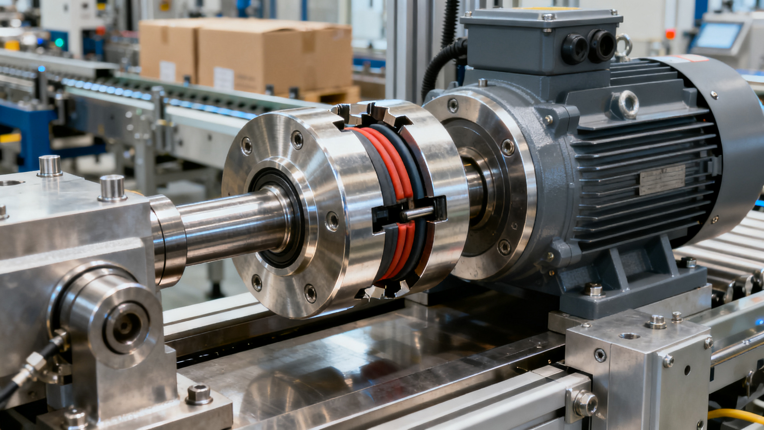
A zero backlash jaw coupling usually combines two metal hubs and a preloaded elastomer spider.
The preload removes free play between the jaws, which helps maintain accurate torque transmission during reversals.
Compared with beam couplings, jaw designs often provide better damping.
Compared with disc couplings, they usually offer more misalignment capacity and lower vibration transmission.
This balance makes the zero backlash jaw coupling common in servo-driven equipment that needs both accuracy and forgiveness.
Still, not every design behaves the same.
Hub material, insert hardness, jaw geometry, and clamp style all change stiffness, damping, and installation stability.
Torque Rating: The First Filter, Not the Final Answer
Torque is the first screen in zero backlash jaw coupling selection, but it should never be the only one.
Start with continuous operating torque, then review peak torque, acceleration torque, and emergency stop events.
Servo applications often create short, repeated torque spikes that exceed average load by a wide margin.
Catalog ratings also vary by manufacturer method, duty cycle, and assumed service factor.
In practice, these checkpoints help:
- Match nominal torque to real operating torque with a realistic safety factor.
- Verify maximum torque against startup, indexing, and jam-release conditions.
- Check whether the torque rating changes with speed, temperature, or elastomer grade.
- Review reversing frequency, because repeated direction changes accelerate insert fatigue.
A zero backlash jaw coupling that survives static torque may still fail in high-cycle servo motion.
Misalignment Control and Its Hidden Cost
Misalignment capacity is often marketed as a benefit, but it should be treated carefully.
A zero backlash jaw coupling can accommodate angular, parallel, and axial misalignment.
That does not mean those limits are ideal for continuous operation.
Running near the published maximum usually increases restoring forces, bearing loads, and insert wear.
More importantly, misalignment can reduce servo performance by adding unwanted radial reaction and non-linear stiffness.
When evaluating a zero backlash jaw coupling, look for the recommended operating zone, not only the allowable limit.
A useful rule is simple: align the shafts as well as the machine allows, then use the coupling for residual error.
What to Measure Before Final Selection
- Angular offset during assembly and at operating temperature.
- Parallel offset caused by machining tolerance or frame movement.
- Axial float from bearing arrangement or thermal growth.
- Shaft runout and clamping surface condition.
Servo Performance: Stiffness, Damping, and Inertia
This is where zero backlash jaw coupling selection becomes more nuanced.
Servo performance depends on the balance between torsional stiffness, damping, and rotating inertia.
Higher stiffness usually improves command response and positional accuracy.
But excessive stiffness can pass motor ripple, resonance, and shock deeper into the mechanism.
Damping helps absorb vibration and smooth reversals, especially in light-load or high-gain axes.
Low inertia matters because the coupling becomes part of the reflected mass the servo must accelerate.
This trade-off explains why the best zero backlash jaw coupling is application-specific.
Common Performance Patterns
Material and Hub Design Choices
Material choice shapes both performance and service life.
Aluminum hubs are common where low inertia is critical.
Steel hubs are heavier, but they can offer higher torque capacity and better durability in demanding cycles.
The elastomer insert also matters.
Harder inserts usually raise stiffness and torque capability.
Softer inserts tend to improve damping and misalignment tolerance.
For a zero backlash jaw coupling, clamp-style hubs are often preferred over set-screw styles in precision servo assemblies.
They reduce shaft damage, improve concentricity, and usually hold better under reversing loads.
Installation and Standards Review
Even a well-selected zero backlash jaw coupling can underperform after poor installation.
Check shaft tolerances, keyway condition if used, clamp screw torque, and hub insertion depth.
Confirm balancing requirements when operating at higher speed.
Review environmental limits too, including oil exposure, humidity, and ambient temperature.
For industrial procurement, documentation remains part of technical selection.
Request dimensional drawings, material declarations, torque data, speed limits, and compliance records where applicable.
Where CE, ISO, or internal machine safety validation applies, traceable product data reduces downstream risk.
A Practical Zero Backlash Jaw Coupling Selection Checklist
- Define continuous torque, peak torque, speed, and duty cycle from actual motion profiles.
- Measure angular, parallel, and axial misalignment under both cold and operating conditions.
- Set the servo priority: maximum stiffness, more damping, or minimum inertia.
- Compare hub material and insert hardness against environmental and dynamic demands.
- Review shaft connection type, mounting envelope, and maintenance access.
- Validate ratings and documents from the supplier, including test data where available.
- Reserve margin for overloads, but avoid unnecessary oversizing that degrades response.
In real projects, that final point is where many decisions go wrong.
A larger zero backlash jaw coupling may look safer on paper, yet it can quietly reduce servo efficiency and tuning stability.
Final Takeaway
The right zero backlash jaw coupling is a system decision, not a simple component purchase.
Torque rating sets the baseline, but misalignment behavior, stiffness, damping, inertia, and installation quality determine real servo results.
When these factors are reviewed together, a zero backlash jaw coupling can improve accuracy, reduce vibration, and support longer drivetrain life.
For technical evaluation, the most reliable path is to compare catalog data against actual motion conditions, operating limits, and compliance needs before release.
That approach leads to better fit, fewer commissioning surprises, and stronger long-term machine performance.
Technical Specifications
- Air Handling Unit Supplier Checklist: Performance Data, Lead Times, and SupportAuthor :Environmental Engineering Director
- Buying Fiberglass Water Tanks Wholesale: Compare Quotes and Delivery CostsAuthor :Environmental Engineering Director
- Choosing an XLPE Power Cable Supplier: Test Reports, Traceability, and Lead TimesAuthor :Grid Infrastructure Analyst
Expert Insights

Chief Security Architect
Dr. Thorne specializes in the intersection of structural engineering and digital resilience. He has advised three G7 governments on industrial infrastructure security.
Related Analysis
- Oct 19, 2026Air Handling Unit Supplier Checklist: Performance Data, Lead Times, and SupportAuthor :Environmental Engineering Director
- Oct 18, 2026Buying Fiberglass Water Tanks Wholesale: Compare Quotes and Delivery CostsAuthor :Environmental Engineering Director
- Oct 17, 2026Choosing an XLPE Power Cable Supplier: Test Reports, Traceability, and Lead TimesAuthor :Grid Infrastructure Analyst
Core Sector // 01
Security & Safety
- Does Power Transmission Maintenance Differ in Desert and Arctic Sites?Author :Heavy Industry Strategist

- Can Industrial Engineering Solutions Reduce Petrochemical Downtime?Author :Heavy Industry Strategist

- What Drives Industrial Roller Chains Price: Material, Pitch, Load, and Supplier FactorsAuthor :Heavy Industry Strategist

- How to Choose a Three Phase Soft Starter for Pumps, Fans, and ConveyorsAuthor :Heavy Industry Strategist

- How to Evaluate a Conveyor Roller Belts Manufacturer for Load, Speed, and Service LifeAuthor :Heavy Industry Strategist

- Power Transmission Systems Pricing: 7 Cost Drivers Buyers Should CompareAuthor :Heavy Industry Strategist

- India Expands BIS ISI Rule for Imported Belts and ChainsAuthor :Heavy Industry Strategist

- Zero Backlash Jaw Coupling Selection Guide: Torque, Misalignment, and Servo PerformanceAuthor :Heavy Industry Strategist