How to Evaluate a Weld Neck Flange Manufacturer for High-Pressure Pipe Projects
Author
Date Published
Reading Time
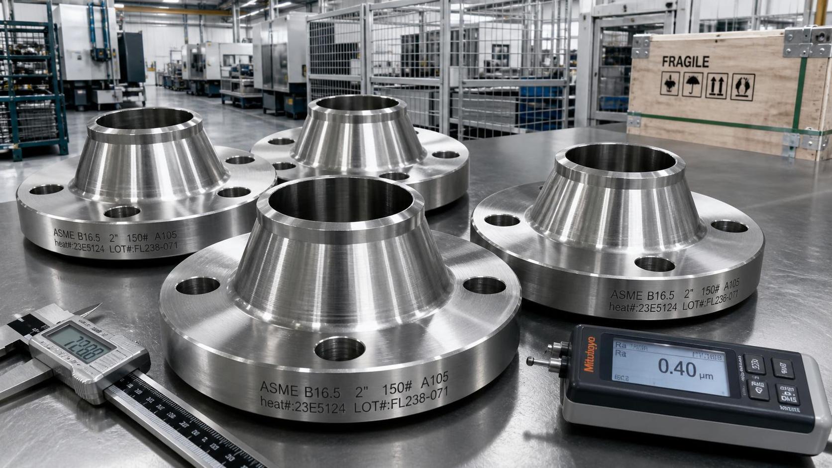
High-pressure pipe work creates a cost profile that extends well beyond the flange unit price. A weld neck flange sits at a stress transition between pipe, weld, gasket, bolts, and connected equipment. When its bore, hub geometry, material condition, or facing is wrong, the resulting cost may include weld removal, delayed hydrotesting, replacement material, inspection scope expansion, or an unplanned shutdown. Evaluation should therefore begin with the project specification and the actual line conditions rather than a catalogue description.
The starting point is to establish the complete flange designation: nominal pipe size, pressure class or PN rating, facing type, material grade, pipe schedule or wall thickness, bore requirement, corrosion allowance, design temperature, governing code, and any supplemental testing. A request that states only “carbon steel weld neck flange” leaves too much room for technically valid but unsuitable supply. High-pressure service often requires controlled hub dimensions, a matching bore, and material properties that remain acceptable at the stated design temperature.
Begin With the Pressure-Temperature Envelope
Pressure class markings are not standalone proof of suitability. ASME B16.5 and ASME B16.47 pressure-temperature ratings depend on the applicable material group, while EN flange systems use their own dimensions, designation practices, and rating concepts. A Class 600 flange is not interchangeable with a PN 100 flange merely because the nominal pressure values appear similar. Bolt circle, bore, flange thickness, facing, and gasket compatibility may differ.
Review the line list, piping class, piping isometric, and equipment nozzle data together. The selected flange must match the piping specification, but it must also work at interfaces where different standards or material systems meet. For example, a flange connected to a pressure vessel nozzle may need a particular facing finish and bolt arrangement specified by the vessel documentation. A nominally compatible flange can still create a field problem if it conflicts with the mating component.
Design pressure should be considered alongside upset conditions, thermal cycles, pressure testing, vacuum exposure where applicable, and corrosive media. The flange material needs acceptable allowable stress at operating temperature, not simply adequate room-temperature tensile strength. Low-temperature applications may call for impact testing. Elevated-temperature lines may require attention to creep-related material behavior, bolting selection, and relaxation of the gasketed joint.
Read Material Traceability as a Chain of Evidence
A reliable weld neck flange manufacturer should be able to connect each finished flange to its originating heat and the material certificate. This connection generally needs to survive cutting, forging, heat treatment, machining, inspection, marking, preservation, and packing. Heat numbers that disappear after machining, certificates that cover a broad shipment without piece-level identification, or markings that cannot be reconciled with packing records create avoidable uncertainty.
For common forged carbon steel flanges, ASTM A105 may be specified; low-temperature service may require ASTM A350 grades; alloy and stainless applications can reference ASTM A182 grades. The governing piping specification controls the exact requirement. Material certificates should be reviewed for chemical composition, mechanical properties, heat treatment status where required, heat number, standard designation, and authorized certification details. A certificate alone is insufficient when the physical marking, purchase order line, and dimensional product do not agree.
Supplementary requirements deserve explicit treatment in the order. These may include normalized or quenched-and-tempered condition, fine grain practice, impact testing temperature, hardness limits, corrosion-resistant alloy overlay restrictions, positive material identification, or restrictions on welding repair. They should not be left as assumptions derived from a general material grade.
Positive material identification is particularly useful where stainless steel, duplex grades, nickel alloys, chrome-moly steels, and carbon steel may be processed in the same environment. The method, sampling basis, acceptance criteria, and record format should be defined in advance. A handheld alloy analyzer can be useful for alloy verification, but it may not establish every element, heat treatment condition, or mechanical property required by the governing standard.
Examine the Actual Forging and Machining Route
Forging capability affects consistency, especially for larger diameters, high pressure classes, unusual bores, and alloy materials. Ask for a clear description of whether the flange is produced from a forging, rolled ring, or another permitted starting form, and how material flow, reduction, heat treatment, and machining are controlled. The answer should align with the applicable material standard and project requirements.
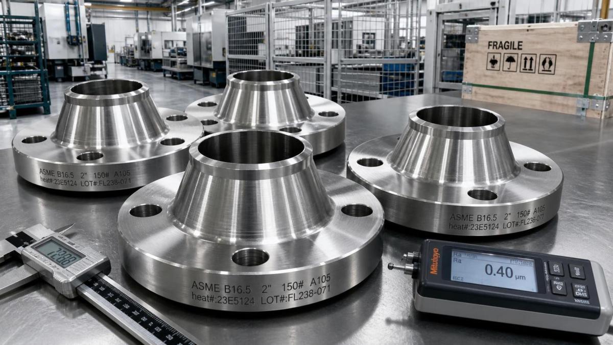
The weld neck hub is not decorative geometry. Its tapered transition distributes stress from the flange rim into the pipe wall, which is one reason this design is widely selected for severe pressure and temperature service. Hub dimensions, flange thickness, bore concentricity, and weld-end preparation must conform to the relevant dimensional standard or approved drawing. A short hub, an incorrect taper, or a bore that does not suit the connected pipe schedule can alter weld fit-up and stress distribution.
Machining controls should cover the raised face, ring-type joint groove where applicable, bolt holes, outside diameter, bore, hub, and weld bevel. Facing type must be verified against the gasket design. Raised-face spiral-wound gasket applications need the specified serration finish; ring-type joint service requires the correct groove profile and surface condition for the selected ring gasket. A visually clean face is not proof that its roughness, groove dimensions, or flatness are acceptable.
Dimensional records become more valuable as the flange moves away from standard catalogue sizes. For custom items, large bores, heavy-wall pipe, or special facing arrangements, require an approved drawing and an inspection report tied to the drawing revision. The report should identify measured values rather than simply state “accepted.”
Separate Documentation Quality From Document Volume
A large document package can obscure rather than resolve technical gaps. The useful package is coherent: purchase order requirements, approved drawings where applicable, material certificates, heat treatment records, dimensional inspection, non-destructive examination reports, pressure test records if required, calibration status for relevant measuring equipment, and a packing list that preserves traceability.
Document review should happen before shipment, not after the material reaches site. Early review allows discrepancies to be corrected while replacement options remain practical. Common issues include a material certificate for the wrong heat, a pressure class mismatch in a marking photograph, a facing designation omitted from a drawing, or a report that cites a standard edition different from the contract requirement.
Standards should be stated precisely. ASME B16.5 addresses pipe flanges and flanged fittings within its scope, while ASME B16.47 applies to certain large-diameter steel flanges. ASTM material standards define material requirements, not every finished dimensional feature. EN systems may require references to the applicable flange, material, and testing standards. ISO references should likewise be linked to the actual contractual requirement rather than used as a general quality label.
Testing Must Reflect the Failure Modes
Forgings may require non-destructive examination depending on material, size, service, or project specification. Ultrasonic examination can be relevant for internal discontinuities; magnetic particle or liquid penetrant examination may be used for surface-breaking indications. The applicable acceptance criteria, examination coverage, personnel qualification requirements, and report format need to be established before production. A report without a stated acceptance standard has limited evaluative value.
Hydrostatic testing of individual flanges is not universally required and should not be assumed. If it is specified, clarify the test arrangement, pressure, hold period, acceptance criteria, drying method, and whether the test can affect corrosion protection or traceability markings. For some configurations, dimensional control, material verification, and appropriate non-destructive examination provide more meaningful evidence than a generic pressure demonstration.
Inspection capability should also be evaluated in practical terms. This includes calibrated dimensional tools, surface roughness measurement where needed, controlled segregation of materials, qualified inspection personnel, and the ability to issue reports before dispatch. Witness or hold points may be appropriate for technically sensitive items, but they should be placed at meaningful stages such as raw material verification, final dimensional inspection, or final release. Excessive hold points can delay production without improving the evidence available for acceptance.
Compare Quotations on a Like-for-Like Basis
A low quotation may exclude work that another offer has included: impact testing, PMI, special bore machining, facing inspection, third-party witnessing, export packing, preservation, or complete documentation. Normalize bids against a single technical schedule. Each line should identify material grade, standard, size, class or PN rating, facing, bore or schedule, testing, marking, certificate type, quantity, and delivery condition.
- Clarify whether quoted weights and dimensions follow the requested standard or an internal pattern. This matters for freight calculations and for fit-up with existing piping.
- Identify any substitutions in material source, forging route, standard edition, or facing designation before order placement. “Equivalent” should be assessed against the project specification, not accepted as a general commercial term.
- Include the cost of nonconformance in the comparison. A shipment that arrives without usable traceability may require quarantine and replacement even when the physical flanges appear sound.
- Review lead time by production stage. Raw material availability, forging capacity, heat treatment, machining, testing, documentation review, and packing can each affect the promised delivery date.
Payment milestones can be tied to objective deliverables when the project allows it. For special flanges, approval of drawings and review of material certificates before final machining may reduce late-stage disputes. The arrangement should preserve adequate flexibility for legitimate production sequencing rather than impose administrative steps unrelated to the technical risk.
Assess Fit-Up Before Material Reaches the Site
Installation risk is often visible in the order data. The weld-end bore should suit the pipe inside diameter and wall thickness, including any required transition machining. Excessive mismatch may require corrective work, while an unapproved thin edge can compromise welding requirements. Welding procedure requirements, preheat needs, post-weld heat treatment, and corrosion protection should be considered where the flange material differs from the adjacent pipe or where alloy service is involved.
Flange face protection matters during transport. Raised faces and ring-type joint grooves can be damaged by loose packing, stacked metal contact, moisture exposure, or abrasive debris. Each flange should have suitable face protection, durable identification, and packaging that prevents contact damage. For stainless and corrosion-resistant alloys, avoid packaging practices that could introduce surface contamination. Long transit periods may also justify a defined preservation method and inspection on receipt.
Receiving inspection should reconcile the physical items with the packing list and released documents. Confirm quantity, tag or heat identification, size, class, facing, visible damage, and certificate availability before the material is dispersed. A discrepancy found after flanges have been issued for fabrication is harder to isolate and may affect more than one spool.
Warning Signs During Technical Evaluation
Several patterns warrant closer scrutiny. One is a quotation that gives a broad standard reference but omits the exact material grade, facing, and bore. Another is a producer that can provide generic sample certificates but cannot explain how certificates will be tied to finished markings. Unexplained differences between the stated forging route and available equipment, or reluctance to supply dimensional inspection results for nonstandard items, also deserve resolution before release.
Be cautious with claims that a flange is “rated” for a service without a stated pressure-temperature basis. The final selection must be verified against the applicable code, material group, and project design conditions. Likewise, a flange carrying familiar markings may still be unsuitable if the markings do not correspond to the ordered standard, heat, or configuration.
The strongest basis for selection is a technically aligned offer supported by traceable material, controlled forming and machining, meaningful inspection evidence, and packaging that preserves the accepted condition through delivery. In high-pressure piping, those details are part of the purchased component, not optional extras attached to it.
Technical Specifications
- Air Handling Unit Supplier Checklist: Performance Data, Lead Times, and SupportAuthor :Environmental Engineering Director
- Buying Fiberglass Water Tanks Wholesale: Compare Quotes and Delivery CostsAuthor :Environmental Engineering Director
- Choosing an XLPE Power Cable Supplier: Test Reports, Traceability, and Lead TimesAuthor :Grid Infrastructure Analyst
Expert Insights

Chief Security Architect
Dr. Thorne specializes in the intersection of structural engineering and digital resilience. He has advised three G7 governments on industrial infrastructure security.
Related Analysis
- Oct 19, 2026Air Handling Unit Supplier Checklist: Performance Data, Lead Times, and SupportAuthor :Environmental Engineering Director
- Oct 18, 2026Buying Fiberglass Water Tanks Wholesale: Compare Quotes and Delivery CostsAuthor :Environmental Engineering Director
- Oct 17, 2026Choosing an XLPE Power Cable Supplier: Test Reports, Traceability, and Lead TimesAuthor :Grid Infrastructure Analyst
Core Sector // 01
Security & Safety
- How to Specify Steel Heavy-Duty Corner Guards for Loading Bays and High-Traffic AreasAuthor :Heavy Industry Strategist

- Selecting Non-Ferrous Metal Plates for Corrosion, Weight, and Formability RequirementsAuthor :Heavy Industry Strategist

- Stainless Steel Welded Tube Applications: Matching Tube Supply to Fabrication NeedsAuthor :Heavy Industry Strategist

- What Maintenance Do Furnace Components Need After 18 Months?Author :Heavy Industry Strategist

- How to Assess Metal Materials for Thermal Cycling in Power BoilersAuthor :Heavy Industry Strategist

- How to Evaluate Aluminum Extrusion Suppliers for Tight-Tolerance Components?Author :Heavy Industry Strategist

- How to Evaluate a Weld Neck Flange Manufacturer for High-Pressure Pipe ProjectsAuthor :Heavy Industry Strategist

- EU REACH Ban Hits Cr(VI)-Coated Steel ImportsAuthor :Heavy Industry Strategist
-Coated Steel Imports")