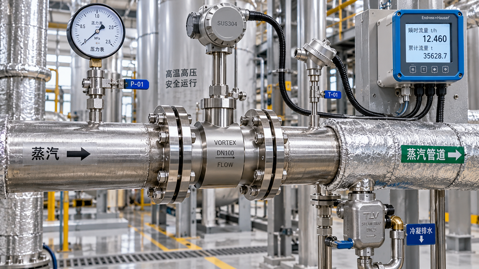
Selecting a steam vortex flow meter requires more than matching a nominal pipe size. Technical evaluators must verify operating pressure, steam temperature, flow range, installation conditions, and required accuracy.
A suitable meter must remain stable at expected loads, capture low-flow operation, withstand credible process excursions, and support maintenance practices throughout its intended service life.
For most evaluations, the decisive question is not whether a vortex meter can measure steam, but whether its selected configuration can measure this specific steam duty reliably.
This guide focuses on the specifications that materially affect selection decisions, including sizing calculations, pressure-temperature ratings, velocity limits, piping requirements, and verification during procurement.
Start with the Operating Envelope, Not the Line Size
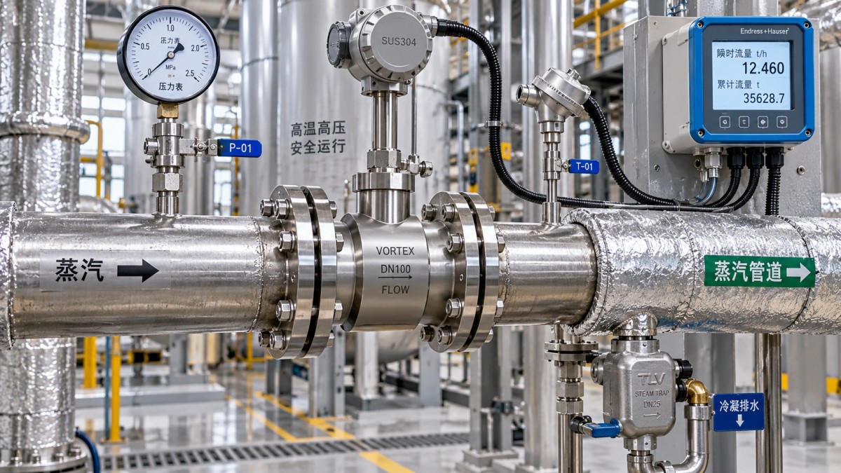
A steam vortex flow meter should be selected against the complete operating envelope: minimum, normal, maximum, startup, upset, and planned future process conditions.
Nominal pipe diameter is only a starting reference. It does not confirm whether steam velocity will generate a measurable vortex signal across the required turndown.
Technical evaluators should request mass flow, pressure, temperature, steam quality, and density data at each relevant operating point before comparing supplier datasheets.
For saturated steam, pressure establishes the saturation temperature and density. For superheated steam, pressure and temperature must both be supplied for accurate density compensation.
When only volumetric flow is available, convert it carefully using the applicable steam state. Standard, actual, and mass flow values are not interchangeable.
The selected meter must cover normal operation with margin while retaining acceptable sensitivity at the lowest credible steam demand, including reduced production periods.
Startup conditions deserve separate attention because cold piping, changing pressure, condensate movement, and temporary high velocities can challenge otherwise appropriate meter selections.
Future capacity expansion can also change the flow profile. A meter selected narrowly around today's normal load may become undersized after process modifications.
Build the evaluation around a documented process data sheet. This prevents vendors from sizing against assumptions that differ from the actual operating duty.
Size the Meter Around Steam Velocity and Required Turndown
Vortex technology measures vortices shed from a bluff body. Signal quality depends on fluid velocity, making velocity range central to steam vortex flow meter sizing.
Each meter design has a minimum velocity for repeatable detection and a maximum velocity limited by pressure loss, vibration, noise, erosion, and sensor performance.
Low-flow performance is often the governing constraint in steam service. At insufficient velocity, the vortex frequency becomes weak, unstable, or indistinguishable from process noise.
Do not assume that a larger bore always provides a safer choice. Oversizing can reduce steam velocity below the meter's minimum measurable threshold.
Conversely, selecting an excessively small bore can create unacceptable permanent pressure loss and may exceed the manufacturer's maximum recommended velocity during peak demand.
Where the process pipe is oversized for measurement conditions, a reduced-bore vortex meter with properly engineered reducers may provide stronger performance than a line-size instrument.
Review the supplier's stated flow range using actual steam conditions. Range tables based on water, air, or standard gas conditions can be misleading.
Turndown should be assessed as the ratio between required maximum and minimum mass flow, then compared with guaranteed accuracy across that range.
A published maximum turndown ratio is not automatically a project guarantee. Confirm the uncertainty at the actual low-flow and high-flow operating points.
Confirm Pressure Ratings at Both Normal and Design Conditions
Pressure evaluation has two separate purposes: confirming meter body integrity and confirming that the instrument can accurately measure steam at the required density.
The pressure rating of the wetted body, flange class, gaskets, bolts, and installation hardware must meet or exceed the project's piping design pressure.
Use the governing piping code and site specification when checking pressure class. A nominal flange designation alone does not establish acceptable temperature-pressure performance.
Pressure-temperature derating is especially important for elevated-temperature steam lines. Allowable pressure for a flange material generally decreases as metal temperature rises.
Evaluate maximum allowable working pressure against credible upset conditions, not just the control-system setpoint. Boiler trips, isolation events, and valve failures may create transient deviations.
For differential-pressure devices, permanent pressure loss can be a major utility concern. Vortex meters usually impose lower loss, but it must still be quantified.
Calculate pressure loss at maximum actual flow, because that is where restrictions become operationally significant and where a reduced-bore selection may need reassessment.
Do not confuse process pressure with meter pressure rating. A meter can survive the pressure while still performing poorly if density and velocity fall outside its measurement range.
Require documentation for pressure-containing materials, flange standard, hydrostatic testing, traceability requirements, and applicable certification before final procurement approval.
Check Temperature Limits Beyond the Sensor Specification
Steam temperature affects every part of the installation: sensor electronics, wetted materials, seals, flange ratings, cable insulation, impulse connections, and thermal expansion behavior.
For superheated steam, verify the maximum continuous process temperature rather than relying on a short-duration temperature limit stated in marketing literature.
Consider the maximum metal temperature at the electronics enclosure. A remote transmitter arrangement may be necessary where radiant heat or pipe conduction is excessive.
Integral electronics simplify installation, but they may not suit high-temperature lines with restricted ventilation, high ambient temperatures, or nearby furnace and turbine equipment.
Temperature limits should include process excursions, steam blowing, cleaning cycles, and abnormal control conditions. These events may exceed normal values by a meaningful margin.
For saturated steam, apparently stable temperature does not eliminate thermal risk. Pressure fluctuations change saturation temperature and can affect density compensation and material loading.
Confirm whether the meter uses integral temperature sensing, an external temperature input, or compensated mass-flow calculations within a remote flow computer.
Integrated pressure and temperature compensation can reduce installation complexity, but it does not replace validation of the actual sensor ranges and accuracy requirements.
Where high-temperature service is critical, request evidence of thermal cycling performance and examine whether the manufacturer specifies insulation restrictions around the meter body.
Choose the Right Measurement Output and Compensation Method
A vortex meter directly measures volumetric flow under actual operating conditions. Steam mass flow requires density calculation using pressure, temperature, or saturation relationships.
For saturated steam, compensated mass flow commonly requires pressure measurement because steam density changes substantially with line pressure, even near saturation temperature.
For superheated steam, both pressure and temperature measurements are normally needed. Omitting either variable can introduce significant mass-flow error during process changes.
Technical evaluators should distinguish between an integrated multivariable steam vortex flow meter and a basic vortex sensor connected to external compensation instruments.
An integrated design can reduce wiring, engineering interfaces, and commissioning effort. External instruments may remain preferable where plant architecture requires centralized calculation.
Review total system uncertainty rather than meter accuracy alone. Pressure transmitter error, temperature sensor error, installation effects, and density calculations all contribute.
For energy accounting, confirm whether the system calculates mass flow only or also determines steam energy using enthalpy values from recognized steam property standards.
Digital protocols such as HART, Modbus, FOUNDATION Fieldbus, or Ethernet-based plant standards should align with the site's control and asset-management strategy.
Specify required outputs early, including pulse, analog, digital communications, diagnostics, local display, and totalization. Retrofitting output capability later can be costly.
Protect Accuracy with Proper Pipework and Installation Conditions
A correctly sized instrument can still deliver poor results if upstream flow disturbances, vibration, liquid carryover, or incorrect orientation compromise the sensing element.
Vortex meters generally need defined straight-pipe lengths upstream and downstream. The required lengths depend on meter design and nearby disturbances such as elbows or valves.
Use the manufacturer's installation guidance for the actual piping arrangement. A generic straight-run rule cannot replace requirements for complex fittings or swirl-producing equipment.
Control valves, pressure-reducing stations, partially open isolation valves, and close-coupled elbows can create turbulence that affects vortex formation and repeatability.
Where straight-run space is limited, assess approved flow conditioners or alternative meter locations. Do not assume a compact installation can be corrected during commissioning.
Steam should be sufficiently dry at the meter location. Condensate droplets can distort measurement, accelerate wear, and create shock loading in poorly drained installations.
Install appropriate drip legs, steam traps, and drainage provisions upstream where condensate accumulation is credible. These components protect both process reliability and measurement stability.
Pipe vibration deserves specific review near compressors, reciprocating equipment, large control valves, and unsupported runs. Mechanical vibration can be interpreted as flow signal noise.
Confirm mounting orientation, access for inspection, cable routing, insulation practices, weather protection, and local display visibility during the engineering review, not after delivery.
Evaluate Accuracy, Repeatability, and Diagnostics in Context
Accuracy claims should be read with the stated reference conditions, flow range, installation assumptions, and compensation arrangement. The headline percentage rarely tells the whole story.
For utility monitoring, repeatability and trend stability may be more valuable than extremely low uncertainty. For custody, allocation, or efficiency guarantees, uncertainty demands increase.
Ask suppliers whether accuracy is expressed as a percentage of reading, a percentage of full scale, or a combined specification. These bases perform differently at low flow.
Repeatability indicates whether the instrument returns the same result under unchanged conditions. It is essential for detecting real process changes and validating energy improvement initiatives.
Modern vortex meters may provide diagnostics for sensor condition, signal strength, electronics health, or abnormal flow behavior. Confirm which diagnostics are actionable on site.
Diagnostic functions are useful only when maintenance teams can access, interpret, and respond to them. Consider integration with existing asset-management and alarm practices.
Calibration documentation should state the method, traceability, test medium, range, and uncertainty. A calibration certificate without these details has limited evaluation value.
For critical duties, establish an acceptance procedure that includes configuration review, loop checks, compensation validation, and comparison against process expectations after startup.
Selection should balance achievable accuracy against the consequences of error. Avoid specifying premium performance where process variability exceeds the meter's practical resolution.
Build a Procurement Specification That Reduces Selection Risk
A robust procurement specification turns engineering intent into comparable vendor submissions. It should prevent bidders from offering technically different configurations under similar descriptions.
Include pipe size, schedule, connection type, steam condition, design pressure, design temperature, normal and extreme flow rates, ambient conditions, and hazardous-area classification.
State whether flow is required as actual volume, compensated mass, energy, or totalized consumption. Define the basis for density, enthalpy, and standard reporting conditions.
Require vendors to provide calculated minimum and maximum velocity, permanent pressure loss, selected bore, guaranteed accuracy, materials, and required upstream and downstream straight lengths.
Request a clear statement of assumptions. This is particularly important when steam quality, pressure variation, turndown, or startup conditions have not been fully characterized.
Materials selection should consider corrosion, external atmosphere, insulation contact, condensate chemistry, and maintenance practices. Stainless steel is common, but suitability remains application-specific.
For regulated facilities, identify mandatory approvals such as CE, UKCA, ATEX, IECEx, SIL-related documentation, pressure equipment compliance, or local electrical certifications.
Compare lifecycle requirements alongside purchase price. Spare parts availability, field verification methods, transmitter replacement, warranty terms, and regional technical support affect long-term cost.
A supplier with a credible steam application record and transparent sizing documentation usually presents less implementation risk than a lower-priced quote with generic data.
A Practical Selection Checklist for Technical Evaluators
Before approving a steam vortex flow meter, confirm that the vendor has sized it using actual steam properties at minimum, normal, maximum, and upset conditions.
Verify that selected bore and flow range maintain measurable velocity at low load without exceeding maximum velocity, noise, pressure-loss, or erosion limits at peak load.
Check pressure class against piping design pressure at design temperature, including derating, gasket compatibility, bolting requirements, and credible transient process scenarios.
Confirm continuous and temporary temperature limits for the sensor, transmitter, cabling, seals, electronics enclosure, and any integral pressure or temperature measurement components.
Review compensation architecture carefully. The most suitable solution must deliver the required mass-flow or energy value with uncertainty appropriate to the commercial or operational use.
Validate installation drawings against straight-run requirements, drainage arrangements, vibration exposure, valve locations, accessibility, insulation rules, and available maintenance clearance.
Request guaranteed performance data, calibration traceability, compliance evidence, materials documentation, and a configuration schedule before issuing the purchase order.
The best steam vortex flow meter is therefore not simply the highest-rated model. It is the verified configuration that fits the process envelope and installation reality.
By treating sizing, pressure, temperature, compensation, and installation as one engineering decision, evaluators can reduce measurement uncertainty and improve long-term steam system control.