How to Select an Industrial Infrared Thermometer for Hot, Moving Equipment
Author
Date Published
Reading Time
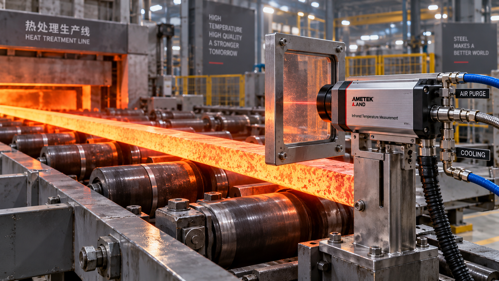
Hot, moving equipment creates a measurement problem that a basic handheld temperature gun often cannot solve. A rotating kiln shell, strip steel, conveyor-carried parts, rolling stock, or a fast reciprocating web may pass through the measurement zone too quickly for a slow sensor, while vibration, dust, steam, and changing surface condition distort the reading. A temperature value that looks stable on a display can still be wrong enough to trigger unnecessary alarms, miss an overheating condition, or lead to poor process control.
The right industrial infrared thermometer is selected from the application outward: define the material surface, target size, speed, measurement distance, temperature band, atmosphere, and required output before comparing instrument specifications. For hot moving equipment, the most important choices are usually spectral response, response time, optical spot size, emissivity handling, environmental protection, and the way the sensor communicates with the control system. A wide temperature range alone is not evidence that an instrument will measure the target reliably.
Start with the measurement event, not the catalog range
Before specifying a sensor, describe what actually passes through its field of view. The relevant question is not simply “How hot is the machine?” It is “What surface must be measured, for how long is it visible, and what else might enter the optical path?”
Consider a heated metal component moving on a conveyor. The sensor may be mounted above the line, aimed through an opening in a guard. Between two parts, it sees the cooler conveyor. If the instrument has a long response time or excessive signal averaging, the displayed temperature may blend the part and conveyor temperatures. A similar issue occurs on rotating equipment when a small hot region passes the sensor once per revolution. The required response depends on the shortest meaningful event, not the average equipment speed.
Record these conditions during the evaluation:
- Target material and finish: oxidized steel, polished metal, painted housing, refractory, rubber, coated web, or another surface.
- Expected temperature range during normal operation, startup, shutdown, and abnormal conditions.
- Minimum target dimension and the maximum available mounting distance.
- Line speed, rotational speed, dwell time within the optical field, and whether gaps occur between targets.
- Viewing angle, possible obstructions, vibration, and access for cleaning or verification.
- Dust, smoke, water vapor, oil mist, flames, hot gases, and ambient temperature around the proposed mounting point.
- Whether the reading supports operator indication, closed-loop control, trending, interlocks, or equipment protection.
This definition often narrows the candidate list quickly. An instrument suited to a broad, slow-moving refractory surface may be unsuitable for a narrow metal strip, even if both applications share the same nominal temperature range.
Match response time to the moving target
Response time is the period an infrared thermometer needs to react to a change in incoming radiation. It should be assessed against the target’s exposure time in the measurement spot. A sensor that reports a value every few milliseconds may still have a response time or filtering setting that smooths a short temperature peak beyond recognition.
Estimate how long the target remains fully inside the spot. For a conveyor application, that time is related to the effective target length in the travel direction divided by conveyor speed. For a rotating shaft or drum, it is tied to angular speed and the width of the measured zone. The sensor should settle rapidly enough to capture the thermal feature that matters, with margin for timing variation and vibration.
Fast response is not automatically better. Very short response settings can make normal process variation, electrical noise, or small changes in surface condition more visible. The practical goal is to preserve the event of interest without producing a signal that is too unstable for the control logic. Confirm whether the quoted response time applies at the required temperature range and spectral band, and whether adjustable averaging is available.
Separate sensor speed from system speed
Technical evaluations should also examine the full signal chain. A fast optical sensor can be limited by a slow analog input, a low update rate in a networked device, controller scan timing, or data historian sampling. If the application requires detecting a brief hot spot, confirm the sensor’s output update rate, the controller’s ability to capture it, and how alarms are configured. An alarm based on a heavily averaged trend may not protect equipment from a short but damaging excursion.
Calculate the spot size at the real mounting distance
Optical resolution, frequently described as distance-to-spot ratio, is one of the most misunderstood specifications. A ratio is useful only when paired with the manufacturer’s defined spot-size relationship and the actual distance. It does not mean the instrument reads only the desired target whenever the target appears larger than a calculated minimum.
The target should normally fill the measurement spot, preferably with allowance for target movement and mounting tolerances. When a small target fills only part of the spot, the instrument measures a combined radiative signal from the target and its background. On a moving production line, that background may be a cooler conveyor, a hot furnace interior, a roller, or open space. The resulting value can shift as the target position changes.
Use the smallest credible target dimension, not the nominal part width, when checking optics. A curved pipe presents a narrower apparent surface than its outside diameter. A rotating component may wander laterally. A strip may track off-center. Equipment vibration can shift the aim point. Where the target is small or the stand-off distance is long, use close-focus optics, a fixed focus matched to the installation distance, or a sighting method that lets the installer verify the measured area.
Choose wavelength based on the surface, not only the temperature
Infrared thermometers infer temperature from emitted radiation. Surface emissivity, the effectiveness with which a material emits radiation compared with an ideal emitter, is central to accuracy. Non-metallic and coated surfaces are often more forgiving than bare metals because their emissivity tends to be higher and less directionally sensitive. Bare, polished, or changing metal surfaces are more difficult. Their apparent temperature can vary with alloy, oxidation, viewing angle, surface finish, and reflected radiation from nearby hot equipment.
The sensor’s spectral wavelength matters because materials behave differently across infrared bands. Short-wavelength instruments are commonly favored for very hot metals and may reduce some emissivity-related sensitivity compared with long-wave measurement, depending on the material and temperature. Longer-wavelength devices can be appropriate for many non-metallic surfaces, painted machinery, refractory, and lower-temperature applications. The correct choice must be tied to the specific target, expected temperature, and optical environment.
A programmable emissivity setting is useful only when the value can be established and maintained. Setting emissivity once during commissioning does not solve a process where the surface progressively oxidizes, becomes wet, accumulates scale, or changes from rough to polished. In these cases, identify whether the purpose is absolute temperature measurement or repeatable detection of deviation. A stable trend can be valuable, but it should not be mistaken for verified surface temperature accuracy.
When ratio measurement may be justified
Two-color, or ratio, pyrometry can be considered when a hot target is partially obscured, its apparent size changes within the field of view, or its emissivity changes in a way that affects both measurement wavelengths similarly. It is often evaluated for hot metals, small targets, and processes with intermittent smoke or dust. It is not a universal cure. It depends on assumptions about the target, requires the target to meet the instrument’s operating conditions, and can produce misleading results when both channels are affected differently by contamination, reflections, or material behavior. Treat it as a specific measurement method to validate, not as an automatic upgrade.
Control reflected energy and the viewing geometry
Hot moving equipment often operates near furnaces, burners, heated guards, and glowing process materials. A low-emissivity surface can reflect this surrounding radiation into the sensor. The result may be an apparent temperature that rises when the background gets hotter, even if the target itself has not changed. Polished metal makes this problem particularly severe.
Viewing angle can either reduce or amplify the error. Avoid aiming directly at a surface angle likely to reflect a furnace opening, burner flame, or radiant panel toward the instrument. A change in sensor location of only a few degrees can materially change the measurement quality. During a site survey, inspect what the target can “see” as well as what the sensor can see. A simple line-of-sight drawing is useful for identifying reflective paths.
Where the process permits, measure an area with a more stable surface condition, such as an oxidized zone, a coating designed for measurement, or a known high-emissivity reference area. Any modification to the asset must be acceptable to the process, maintenance, and safety requirements. Do not rely on tape, paint, or coatings in locations where heat, speed, contamination, or material compatibility could make them unsuitable.
Design the installation around the environment
An industrial infrared thermometer is an optical device, so a clean, stable line of sight is part of the measurement system. Dust on the lens, vapor in the path, and oil film on a protective window can attenuate radiation. The effect may appear gradually as drift rather than a sudden instrument failure. A sensor installed close to a hot process can also exceed its ambient temperature limit even when its measured target range is appropriate.
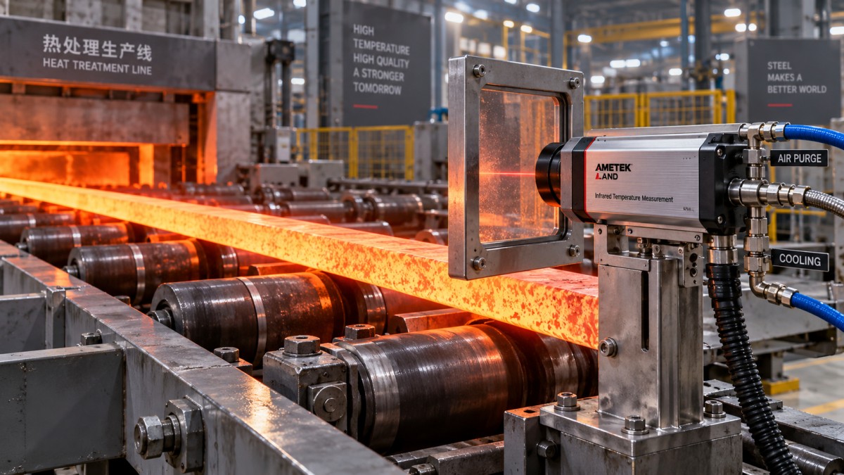
Review the enclosure rating required for washdown, dust ingress, outdoor exposure, and mechanical impact. Confirm the allowed ambient temperature at the sensor body, cable temperature limits, and whether cooling, an air purge, or a protective housing is needed. A purge can help keep contaminants away from the lens, but poorly directed air can carry debris across the optical path or cool a nearby low-mass target. Mounting hardware should resist vibration and permit controlled alignment without placing personnel in an unsafe access position.
Window materials deserve separate attention. A window that protects the sensor may not transmit the relevant infrared wavelength effectively, especially if it is selected only for visible transparency. Verify compatibility between the window material, thickness, wavelength range, operating temperature, contamination exposure, and cleaning method. A scratched or coated window becomes another variable in the measurement uncertainty.
Select outputs that support the decision being made
For local checks, a handheld unit with appropriate optics and adjustable emissivity may be enough. Continuous monitoring of hot moving equipment usually calls for a fixed sensor with a stable mount and an output suitable for the existing automation architecture. Analog output can be straightforward for a controller input, while digital communication can provide diagnostics, configuration access, and more detailed signal handling. The preferred interface depends on what the receiving system can reliably use.
Do not specify only the communication protocol. Ask what happens when the target is absent, the lens becomes contaminated, the measured signal is outside range, the sensor loses power, or communications fail. A temperature signal may be valid-looking during a target gap unless the system uses a trigger, presence sensor, timer, or logic to distinguish product from background. For protection functions, define the required failure behavior before installation rather than after the first unexplained alarm.
Build acceptance testing into the purchase decision
The most defensible selection process includes a site-representative validation plan. Bench testing at room conditions rarely reproduces a hot, reflective, dusty, moving application. During commissioning, verify the actual spot location, sensor-to-target distance, target dwell time, signal behavior during gaps, and the influence of normal process changes. Compare against a reference method only when that reference is suitable for the material, access conditions, and temperature range.
Document the selected emissivity or ratio settings, focus distance, mounting angle, filtering, alarm thresholds, cleaning interval, and conditions under which the reading should not be trusted. This record matters when a sensor is replaced, a line is modified, or a process engineer later compares historical trends.
A suitable instrument is one that measures the intended surface at the required speed and distance while remaining stable in the actual plant environment. When the target is bare metal, highly reflective, intermittently hidden, or safety-critical, the evaluation should include application-specific confirmation of wavelength, emissivity approach, optics, and failure handling before the measurement is used for automated decisions.
Technical Specifications
- Air Handling Unit Supplier Checklist: Performance Data, Lead Times, and SupportAuthor :Environmental Engineering Director
- Buying Fiberglass Water Tanks Wholesale: Compare Quotes and Delivery CostsAuthor :Environmental Engineering Director
- Choosing an XLPE Power Cable Supplier: Test Reports, Traceability, and Lead TimesAuthor :Grid Infrastructure Analyst
Expert Insights

Chief Security Architect
Dr. Thorne specializes in the intersection of structural engineering and digital resilience. He has advised three G7 governments on industrial infrastructure security.
Related Analysis
- Oct 19, 2026Air Handling Unit Supplier Checklist: Performance Data, Lead Times, and SupportAuthor :Environmental Engineering Director
- Oct 18, 2026Buying Fiberglass Water Tanks Wholesale: Compare Quotes and Delivery CostsAuthor :Environmental Engineering Director
- Oct 17, 2026Choosing an XLPE Power Cable Supplier: Test Reports, Traceability, and Lead TimesAuthor :Grid Infrastructure Analyst
Core Sector // 01
Security & Safety
- Choosing a Bluetooth Total Station: Software Compatibility and Connection RangeAuthor :Precision Metrology Expert

- Material Testing Standards: ASTM E8 vs. ISO 6892-1 for Metal Tensile TestsAuthor :Precision Metrology Expert

- How to Verify Accuracy in Industrial Measurement Data and Test ReportsAuthor :Precision Metrology Expert

- Selecting a Steam Vortex Flow Meter: Sizing, Pressure, and Temperature LimitsAuthor :Precision Metrology Expert

- How to Select an Industrial Infrared Thermometer for Hot, Moving EquipmentAuthor :Precision Metrology Expert

- How to Evaluate a Precision Measurement Equipment Manufacturer for Critical TolerancesAuthor :Precision Metrology Expert

- How to Select an Emissions Monitoring System Analyzer for Compliance ReportingAuthor :Precision Metrology Expert

- Portable Gas Monitor Calibration: How Often Is It Needed for Safe Confined-Space Work?Author :Precision Metrology Expert