How to Select Surge Protection Devices for Lightning-Prone Mines
Author
Date Published
Reading Time
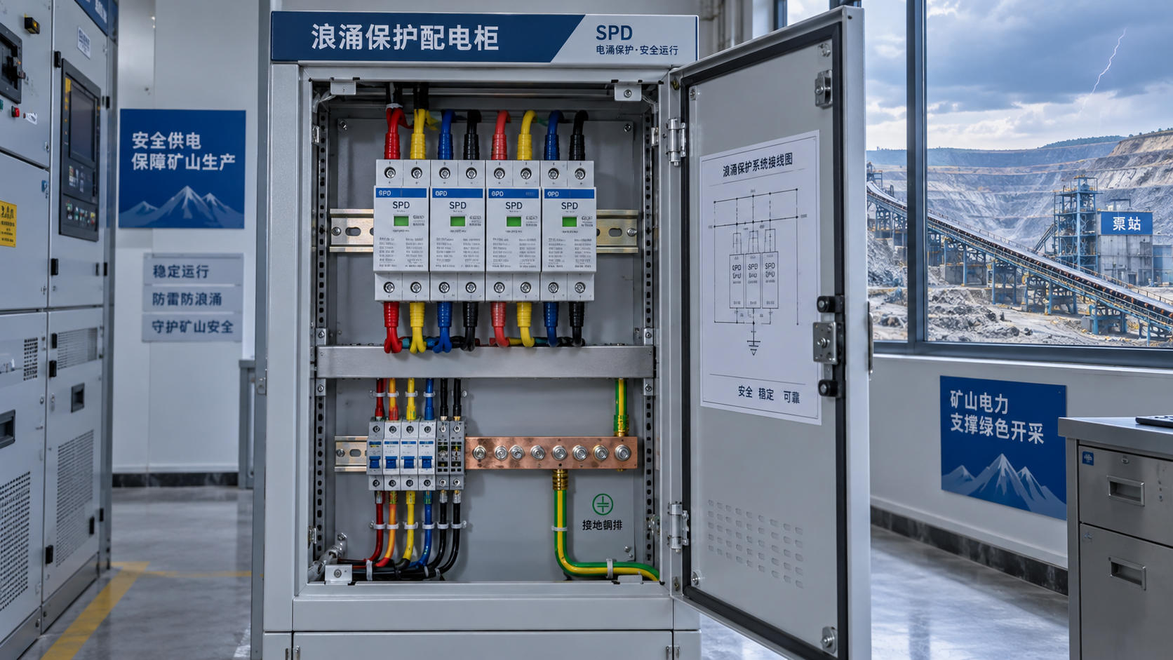
At a lightning-prone mine, a storm can disrupt more than the incoming power supply. Long feeders to pumps, exposed conveyor structures, and copper communications cables can carry transient voltages into equipment far from the strike location. Selecting surge protection devices for lightning prone mining sites therefore starts with the electrical network and lightning exposure—not the largest discharge-current rating in a catalog.
Use a coordinated protection design: select lightning-current-capable protection where the risk assessment identifies possible lightning-current entry, downstream protection at distribution boards, and compatible protection for sensitive equipment and conductive signal lines. Verify system voltage, earthing arrangement, protection level, fault-current compatibility, environmental suitability, and installation requirements before specifying devices. An SPD cannot compensate for missing equipotential bonding or replace an external lightning protection system.
Map the surge paths before choosing devices
Begin with the site single-line diagram, the earthing design, and the routes of power and communications cables. A utility incomer is only one entry point. Remote substations, overhead feeders, antenna cables, instrumentation circuits, and cables between buildings can introduce surges or connect areas whose earth potentials rise differently during lightning activity.
Record the following information for each protection location:
- Nominal voltage, frequency, conductor configuration, and maximum expected operating voltage.
- Earthing arrangement, including TN, TT, or IT systems and any resistance-grounded networks.
- Available prospective short-circuit current and upstream protective devices.
- Overhead or buried cable routes, building-to-building connections, and external lightning protection arrangements.
- Connected equipment impulse withstand ratings and the operational consequences of failure.
- Dust, water, temperature, corrosion, vibration, and hazardous-area conditions.
Consider a dewatering pump supplied from a remote distribution board. Protecting only the main switchroom may leave the pump controls exposed to surges induced along the feeder or entering through a level-sensor cable. The selection task is to identify those paths and coordinate protection at the relevant boundaries, not simply duplicate the main-board SPD everywhere.
Underground location does not eliminate exposure. Surface-to-underground power and communications circuits can transport disturbances into underground equipment. Conversely, buried cables should not automatically be treated as immune to lightning-related transients.
Assign protection duties at each boundary
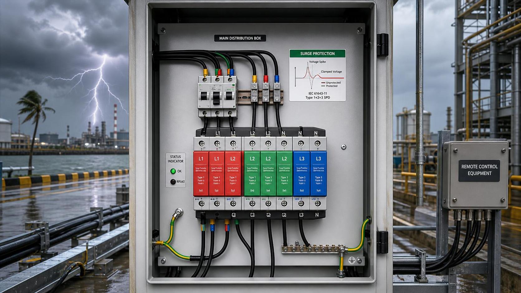
Under the IEC framework, Type 1 SPDs are tested with a lightning-current impulse, commonly expressed using the 10/350 microsecond waveform. They are used where partial lightning currents may enter the electrical installation. Type 2 SPDs are tested with an 8/20 microsecond current waveform and address induced lightning surges and switching transients at distribution locations. Type 3 devices provide equipment-level protection and require coordination with upstream protection.
These are selection directions, not an automatic device schedule. The lightning risk assessment, installation rules, and network configuration determine the final requirements. A combined Type 1+2 unit may address more than one duty at a boundary, but it does not necessarily remove the need for downstream protection.
Do not assume that IEC and UL type designations are interchangeable. UL 1449 classifications describe permitted installation locations and associated requirements; their numbering does not directly reproduce IEC test classes. Specifications should name the applicable standard and required performance rather than request “Type 1” without context.
Match voltage and earthing before comparing surge ratings
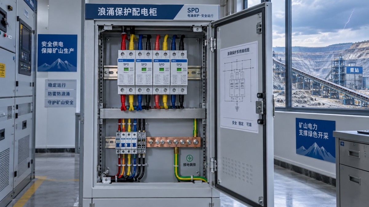
Maximum continuous operating voltage, Uc, must suit the voltage actually applied across each protection mode. Selecting it from the line-to-line voltage alone can produce the wrong result. Confirm whether the device protects phase-to-neutral, phase-to-earth, neutral-to-earth, or another combination, and use the manufacturer’s connection arrangement for the network concerned.
A lower Uc is not automatically better protection. If normal voltage variation or a temporary overvoltage exceeds the device’s capabilities, the SPD may disconnect or fail. An unnecessarily high Uc can also produce a protection level unsuitable for sensitive equipment. Compare continuous-voltage suitability and temporary-overvoltage behavior together.
Mining networks require particular care where IT or resistance-grounded systems are used. During an earth fault, the voltage of healthy conductors to earth can rise. An SPD designed for a different earthing arrangement may not tolerate that condition. Compatibility with insulation monitoring and earth-fault protection must also be confirmed rather than inferred from a familiar nominal voltage.
For TT systems, the protection arrangement must account for the relationship between neutral, earth, and residual-current protection. Use a connection topology approved for that application under the governing installation rules. Do not substitute a different pole configuration because its catalog current rating looks equivalent.
Read discharge capacity and protection level together
Discharge ratings describe different test duties. For IEC Type 1 devices, impulse discharge current, Iimp, relates to the lightning-current test. For Type 2 devices, nominal discharge current, In, and maximum discharge current, Imax, relate to the specified 8/20 microsecond tests. A large Imax value does not demonstrate Type 1 lightning-current capability.
Check whether a quoted rating applies per pole, per protection mode, or to the complete device. Those values are not interchangeable. The required lightning-current duty should follow the lightning protection design and expected current sharing, including connected services and bonding paths; it should not be estimated solely from local storm frequency.
Voltage protection level, Up, is central to equipment protection. Compare the declared value with the equipment’s impulse withstand rating, allowing for the additional voltage developed across installation conductors. A suitable catalog Up does not guarantee that the same voltage appears at the equipment terminals.
Where UL-rated products are specified, assess the declared voltage protection rating under the applicable test conditions rather than treating it as numerically identical to an IEC Up value. Ask for documentation that makes the rating basis and protection modes clear.
Coordination matters as much as individual ratings. A downstream device with a lower limiting voltage may absorb excessive energy if the upstream and downstream stages are incompatible. Use manufacturer-supported coordination information for the actual devices and installation arrangement, including any required separation or decoupling.
Installation can defeat an otherwise sound selection
SPD connection conductors develop inductive voltage during a fast surge. Long leads, large loops, and indirect routes to the bonding system can therefore raise the effective protection level. Place devices close to the relevant conductors and bonding connection, and follow the manufacturer’s permitted wiring arrangements and the applicable installation rules.
Review panel layout before procurement is finalized. A crowded enclosure that forces long SPD leads may need redesign. Suitable through-connection arrangements can reduce connection effects where supported by the product, but conductor sizes, terminal capacities, and protective-device requirements still apply.
Bonding must address all relevant conductive services. Adding an isolated earth electrode for an SPD is not a substitute for coordinated equipotential bonding and may create dangerous potential differences. Earthing and lightning protection changes require engineering review, especially where mine earth-fault protection depends on a defined network arrangement.
Keep protected and unprotected wiring appropriately separated to limit recoupling. Signal-cable shields, enclosure bonds, and communications protectors need a consistent grounding strategy; an improvised connection can undermine protection or introduce operating problems.
Verify safe failure behavior and mining conditions
An SPD can reach end of life after repeated stress, a severe event, or abnormal power-frequency voltage. Selection must therefore cover what happens when it no longer functions—not just what it does during a surge.
- Short-circuit compatibility: verify the declared short-circuit rating under the applicable standard against the available fault current at the installation point.
- Backup protection: confirm required fuse or circuit-breaker types, ratings, and any conditions attached to the SPD’s fault-current rating.
- Follow-current interruption: where relevant to the technology, check capability under the actual network conditions.
- Disconnection and indication: require clear end-of-life status and consider remote contacts for inaccessible or operationally important boards.
Environmental suitability includes the enclosure and installation, not only the SPD module. Confirm temperature limits, altitude restrictions, humidity, condensation control, and resistance to dust or corrosive exposure. High enclosure temperatures can exceed product limits even when outdoor ambient conditions appear acceptable.
Hazardous mining areas require a separate suitability check. Ordinary electrical safety certification does not establish suitability for explosive gas or dust atmospheres. Verify the applicable hazardous-area requirements for the complete assembly and installation location. Protection added to intrinsically safe circuits must preserve the approved circuit parameters and arrangement.
Protect control and communications without impairing operation
Power-side SPDs do not protect every interface on a PLC, telemetry unit, or instrument. A controller may remain powered while a connected copper network port is damaged. Identify each conductive connection crossing buildings, outdoor structures, or bonding zones and assess protection at the relevant entry points.
Signal SPDs must match the circuit. Check operating voltage, permissible series resistance, current, bandwidth, capacitance, and connection format. Analog measurement loops, digital networks, and antenna feeders impose different requirements. Ethernet protection also needs compatibility with the required data rate and any power-over-Ethernet function.
For low-level measurement circuits, evaluate the protector’s effect on accuracy and signal integrity. For safety-related controls, confirm that added protection does not invalidate the system’s functional requirements. Optical fiber can remove a conductive data path, but metallic armor, power conductors, and connected equipment supplies still require assessment.
Turn the design into a verifiable procurement specification
Request evidence against the required duties rather than accepting a broad “lightning protection” claim. The supplier submission should identify the applicable product standard, connection diagram, protection modes, Uc, Up or the relevant protection rating, discharge ratings, short-circuit conditions, backup protection, environmental limits, and supported coordination arrangements. Verify certification or listing scope for the exact model offered.
Before energization, qualified personnel should confirm that installed devices match the approved schedule, connections follow the specified topology, bonding paths are sound, and status contacts reach the monitoring system where required. Work on mining electrical installations must follow site isolation and electrical safety procedures.
Include inspection and replacement access in the design. Check indicators during planned maintenance and after significant lightning events, investigate alarms, and keep compatible replacement modules where downtime justifies them. Reassess the protection schedule when feeders, communications routes, earthing arrangements, or operating voltages change: an SPD selected for the original network may no longer suit the modified installation.
Technical Specifications
- Nucor Raises Hot-Rolled Coil Spot Price by $15 to $1,270 per Short TonAuthor :
- Choosing an Industrial Electrical Infrastructure Supplier: Compliance and Lead TimesAuthor :Grid Infrastructure Analyst
- US Commerce Opens Changed Circumstances Review of Mexican Heavy-Walled Rectangular Welded Carbon Steel PipeAuthor :Heavy Industry Strategist
Expert Insights

Chief Security Architect
Dr. Thorne specializes in the intersection of structural engineering and digital resilience. He has advised three G7 governments on industrial infrastructure security.
Related Analysis
- Oct 27, 2026Nucor Raises Hot-Rolled Coil Spot Price by $15 to $1,270 per Short TonAuthor :
- Oct 27, 2026Choosing an Industrial Electrical Infrastructure Supplier: Compliance and Lead TimesAuthor :Grid Infrastructure Analyst
- Oct 26, 2026US Commerce Opens Changed Circumstances Review of Mexican Heavy-Walled Rectangular Welded Carbon Steel PipeAuthor :Heavy Industry Strategist
Core Sector // 01
Security & Safety
- Outdoor Vacuum Circuit Breaker Selection: Voltage, Fault Duty, and Site ConditionsAuthor :Grid Infrastructure Analyst

- Choosing a Surge Protection Device Factory: Testing and Traceability ChecksAuthor :Grid Infrastructure Analyst

- How to Select Surge Protection Devices for Lightning-Prone MinesAuthor :Grid Infrastructure Analyst

- Can SPDs Handle Repeated Voltage Spikes in Tropical Grids?Author :Grid Infrastructure Analyst

- How to Evaluate IEC-Compliant Power Protection Devices for Industrial PanelsAuthor :Grid Infrastructure Analyst

- How to Choose Smart Industrial Control Equipment for Harsh Plant EnvironmentsAuthor :Grid Infrastructure Analyst

- EU EMC Update Triggers Re-Certification for BreakersAuthor :Grid Infrastructure Analyst

- How to Select the Right SPD for Solar Inverter Protection in PV Systems?Author :Grid Infrastructure Analyst