How to Select Industrial Emission Control Systems for High-Dust Manufacturing Lines
Author
Date Published
Reading Time
Start selection with the process source, not the collector catalogue. A high-dust line can fail an otherwise capable emission control system when the design basis treats all dust as a single material and all airflow as constant. Grinding fines, kiln carryover, dry bulk transfer dust, metallic particles, fibrous material, and sticky process residues behave differently in ductwork, filters, hoppers, and discharge equipment. The system must control the actual release points while remaining stable through production changes, cleaning cycles, and upset conditions.
For industrial emission control, the first decision is whether the principal challenge is capture, transport, separation, final filtration, gas treatment, or a combination of these functions. A high-efficiency filter cannot compensate for a poorly enclosed transfer point, an undersized branch duct, or an unstable fan operating point. Likewise, adding airflow without examining hood geometry can increase energy use and pull excess conditioned air from the building without materially improving capture.
Build the design basis from the dust-generating process
Map every point where material is dropped, cut, conveyed, screened, discharged, cleaned, or thermally processed. Record the material condition at each point: dry, damp, hot, abrasive, corrosive, fibrous, combustible, electrostatically charged, or prone to agglomeration. The same nominal material can require different control methods after crushing than after drying, because particle-size distribution, moisture, and liberation from the parent material have changed.
Sampling should distinguish between bulk material data and airborne dust data. Bulk product specifications often understate the fine fraction that reaches the collector. Fine particles carry farther, remain suspended longer, and can create a disproportionate pressure-drop burden on filter media. A sample taken from a settled floor deposit also does not represent the material loading entering a hood during a drop event. Where production is variable, collect information across representative grades, throughput levels, and operating states rather than basing the design on a single shift observation.
Important process inputs include the maximum and typical feed rate, material temperature, moisture range, density, particle morphology, and expected contaminant concentration. Identify batch operations, purge events, intermittent dumps, and upstream failures that send unusually heavy loads downstream. These short-duration events often determine hopper capacity, inlet design, filter cleaning demand, and whether a pre-separator is justified.
Capture performance begins at the source
Local exhaust hoods should be evaluated as part of the machine or transfer arrangement. The hood must overcome air currents produced by falling material, moving conveyors, rotating tools, thermal buoyancy, vehicle movement, and nearby supply-air systems. An opening that appears small on a drawing can become a large uncontrolled path when guards are raised, access panels remain open, or a belt conveyor requires clearance along both sides.
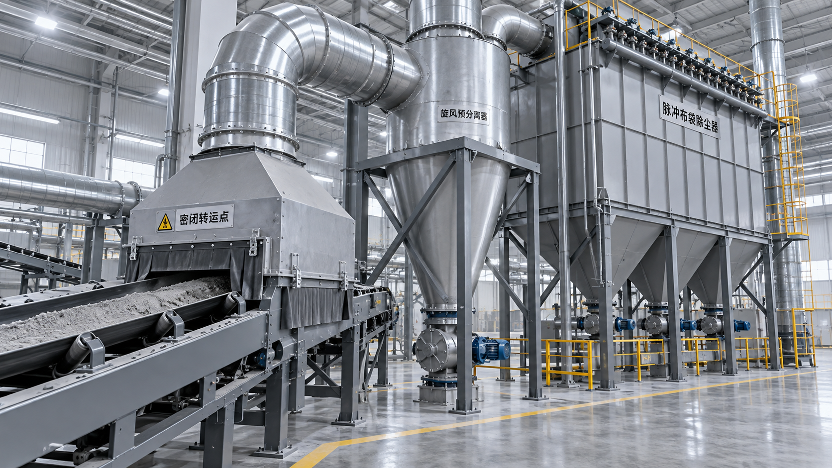
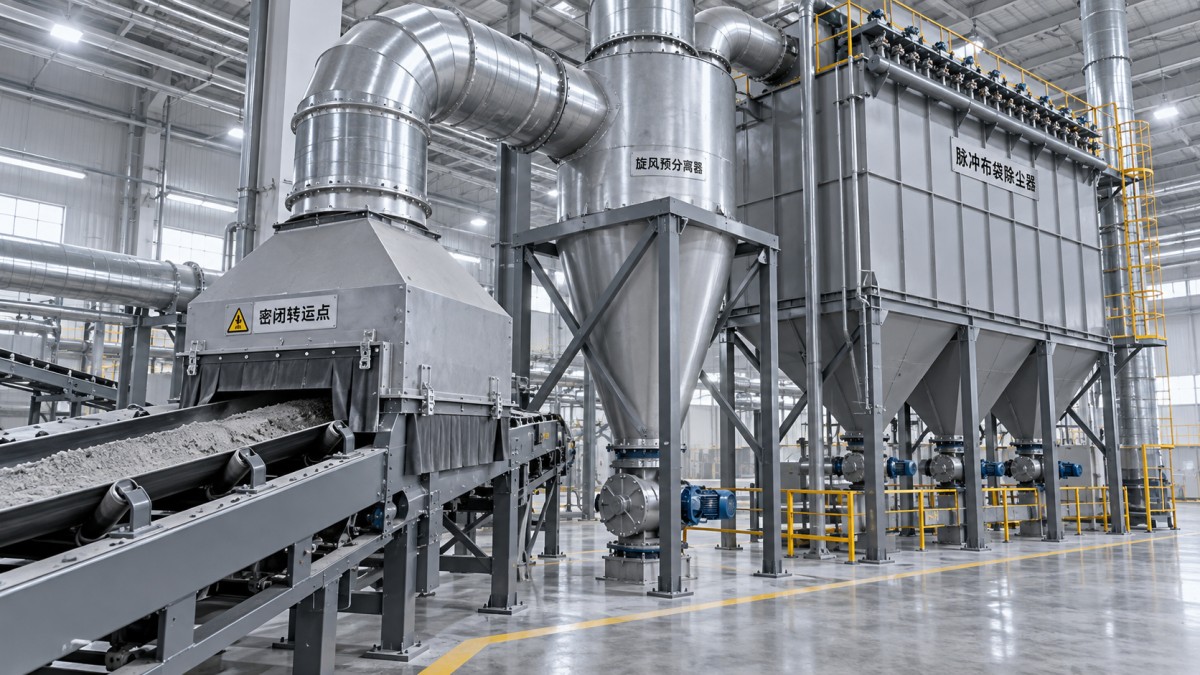
Enclosure is usually the most reliable way to reduce required exhaust volume. Adding skirts, baffles, flexible curtains, or a receiving enclosure may lower the airflow needed for capture and reduce the size of the downstream system. These features need maintenance access and sufficient clearance from moving equipment; poorly placed curtains can wear rapidly or interfere with material flow. For conveyor transfer points, examine the trajectory of the material stream and the direction in which displaced air leaves the enclosure. Extracting from the wrong location can pull dust through the worker-facing opening instead of containing it.
Do not specify branch airflow solely from a velocity target. Airflow must be compatible with hood losses, open area, capture distance, duct transport needs, and the selected fan curve. A duct velocity that prevents settling in a horizontal run may be inappropriate at a fragile product pickup or may cause unnecessary erosion at an abrasive source. The design needs enough velocity to keep the anticipated dust mobile, while avoiding excessive pressure loss, noise, and wear.
Choose separation and filtration around the dust burden
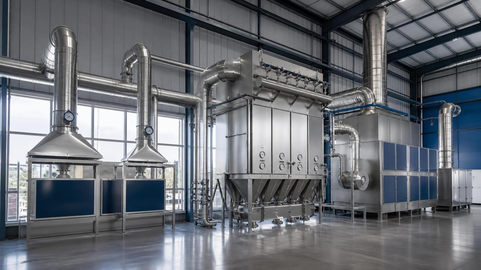
High-dust systems commonly benefit from staged separation. A drop-out chamber, inertial separator, or cyclone can remove a coarse, abrasive fraction before it reaches the final filter. This arrangement is most useful when the inlet loading is high and the coarse fraction is genuinely separable. It is less useful when the particulate is predominantly fine, low-density, or irregularly shaped, because the pre-separator may add pressure loss without removing enough mass to alter filter loading.
Filter media selection should reflect chemistry and operating temperature, not only nominal filtration efficiency. Surface-treated media can improve dust release where a stable cake is desirable, while membrane-laminated media can limit penetration of fine particles into the substrate. High-temperature service requires the full assembly to be reviewed, including gaskets, cages, seals, pulse valves, wiring, and any insulation. A filter fabric that tolerates the temperature on paper does not solve failure at a lower-rated adjacent component.
For hygroscopic or sticky dust, assess dew point and condensation risk at the collector inlet. Cold spots in ductwork, a fan drawing in humid ambient air, or an uninsulated housing can turn a free-flowing powder into deposits that blind media and bridge hoppers. Heated or insulated equipment, tempered dilution air, and altered process sequencing may be more effective than increasing cleaning pressure.
Pressure drop tells a more useful story than a single efficiency figure
Collection efficiency must be considered at the regulated emission point and under the expected range of operating conditions. It is only one performance measure. The pressure-drop profile across the collector affects fan power, airflow at distant hoods, filter cleaning frequency, and the warning time available before production is affected.
Specify an acceptable operating pressure-drop band rather than treating the maximum differential pressure as the normal condition. A collector operating near its upper limit may still show acceptable outlet performance while source capture deteriorates because total system resistance has reduced airflow. Conversely, unusually low pressure drop can indicate damaged media, leaks, ineffective cleaning controls, or an incorrect sensor connection. Differential-pressure transmitters should be installed so that impulse lines do not plug and readings are not distorted by pulsation.
Fan selection requires the completed system resistance curve, including hood losses, duct friction, elbows, dampers, silencers, pre-separation equipment, filter loading range, and outlet arrangement. Allowing an arbitrary pressure margin can create a fan that is difficult to control and wastes energy. Selecting exactly at one calculated duty point leaves little tolerance for duct modifications, media aging, or changed production. Variable-speed control can accommodate normal operating variation, but it must not reduce transport velocity below the level needed to keep dust from settling.
Combustible dust changes the project scope
When dust could present a combustible-dust hazard, obtain material-specific hazard information early. Particle size, moisture, contamination, oxidizability, and process temperature affect the assessment. Do not infer the risk from the appearance of the bulk material or assume that an inert-seeming mineral cannot contain combustible contamination from binders, coatings, lubricants, or mixed production streams.
The control strategy may affect enclosure design, duct routing, isolation between connected vessels, ignition-source management, collector location, explosion venting or suppression, and discharge equipment. These elements must work as an integrated arrangement. Installing a protective device on the collector alone may leave connected ducts, bins, or indoor equipment exposed to pressure propagation. Local legal requirements and the applicable hazard analysis should govern the final configuration.
Design discharge as part of the collection system
A hopper is not merely a storage cone beneath a filter. Dust must leave it continuously enough to prevent accumulation from reaching the media, obstructing the inlet, or being re-entrained by the gas stream. Hopper angle, internal surface condition, material cohesion, temperature, and vibration all influence flow. Fine or damp dust can bridge even when a hopper has a steep geometry. Abrasive material can rapidly damage rotary valves, screw conveyors, and transition sections.
Choose the discharge device around required air sealing, material flow behavior, and the destination of the collected dust. A rotary airlock may suit a dry, free-flowing material but needs wear control and adequate clearance management. A screw conveyor provides metering but can compact certain materials. Pneumatic conveying introduces another airflow system that must be accounted for. Maintenance access to the discharge device matters because a blocked hopper can disable the entire emission control train.
Make maintenance conditions visible during selection
Ask for the physical layout before finalizing collector type and location. Filter replacement clearance, roof load limits, crane access, platform design, weather exposure, compressed-air quality, instrument access, and isolation points should be resolved in the equipment arrangement. A compact collector can become expensive to maintain when every element change requires removing ductwork or working through a restricted platform opening.
Compressed-air cleaning systems deserve the same scrutiny as the collector housing. Water or oil in the pulse-air supply can degrade media and valves. Insufficient receiver capacity can produce weak cleaning during peak demand. Excessive pulse pressure may damage media or waste air without improving release. Trend differential pressure, fan speed, airflow, pulse frequency, hopper level, and outlet-monitor status together; a single alarm rarely explains the underlying condition.
Acceptance testing should verify more than a clean-filter airflow reading. Confirm capture at representative release points, fan operation across expected filter loading, absence of visible duct leakage, hopper discharge continuity, control interlocks, and monitoring signals. Establish baseline values after commissioning so later changes in pressure drop, energy use, or emissions can be interpreted against a known operating condition. The selected system is suitable when its capture arrangement, air-moving capacity, separation stages, discharge path, protection measures, and maintenance access remain compatible with the real production envelope.
Technical Specifications
- Air Handling Unit Supplier Checklist: Performance Data, Lead Times, and SupportAuthor :Environmental Engineering Director
- Buying Fiberglass Water Tanks Wholesale: Compare Quotes and Delivery CostsAuthor :Environmental Engineering Director
- Choosing an XLPE Power Cable Supplier: Test Reports, Traceability, and Lead TimesAuthor :Grid Infrastructure Analyst
Expert Insights

Chief Security Architect
Dr. Thorne specializes in the intersection of structural engineering and digital resilience. He has advised three G7 governments on industrial infrastructure security.
Related Analysis
- Oct 19, 2026Air Handling Unit Supplier Checklist: Performance Data, Lead Times, and SupportAuthor :Environmental Engineering Director
- Oct 18, 2026Buying Fiberglass Water Tanks Wholesale: Compare Quotes and Delivery CostsAuthor :Environmental Engineering Director
- Oct 17, 2026Choosing an XLPE Power Cable Supplier: Test Reports, Traceability, and Lead TimesAuthor :Grid Infrastructure Analyst
Core Sector // 01
Security & Safety
- Air Handling Unit Supplier Checklist: Performance Data, Lead Times, and SupportAuthor :Environmental Engineering Director

- How to Select Industrial Emission Control Systems for High-Dust Manufacturing LinesAuthor :Environmental Engineering Director

- Environmental Technologies for Heavy Industry: Choosing Cleaner Production SolutionsAuthor :Environmental Engineering Director

- Selecting Air Compliance Equipment for Dust, Fumes, and VOC ControlAuthor :Environmental Engineering Director

- EU Rule Tightens EN 1822-2 for Industrial Air PurifiersAuthor :Environmental Engineering Director

- EU Eco-Design Rules Tighten for Air PurifiersAuthor :Environmental Engineering Director

- Low-Maintenance Dust and Fume Control Systems: Best Options for Welding ShopsAuthor :Environmental Engineering Director

- EPA Sets VOC Labeling Rule for Air PurifiersAuthor :Environmental Engineering Director