Industrial Electrical Infrastructure Design: Key Components, Load Planning, and Safety Codes
Author
Date Published
Reading Time
Industrial electrical infrastructure design shapes far more than cable routes and equipment lists. It determines whether a plant can expand without disruption, absorb fluctuating demand, and remain compliant under strict safety review.
That is why the subject now sits closer to business continuity than to isolated engineering detail. In heavy industry, a weak electrical backbone can delay commissioning, shorten asset life, and create avoidable risk across operations.
A sound approach connects power reliability, load growth, protection strategy, maintainability, and code alignment from the earliest design decisions. It also supports the wider expectations now placed on global industrial projects.
Across the sectors tracked by Global Industrial Core, electrical planning increasingly intersects with safety, instrumentation, environmental control, and procurement quality. The result is a more integrated view of industrial electrical infrastructure design.
What the design scope really includes
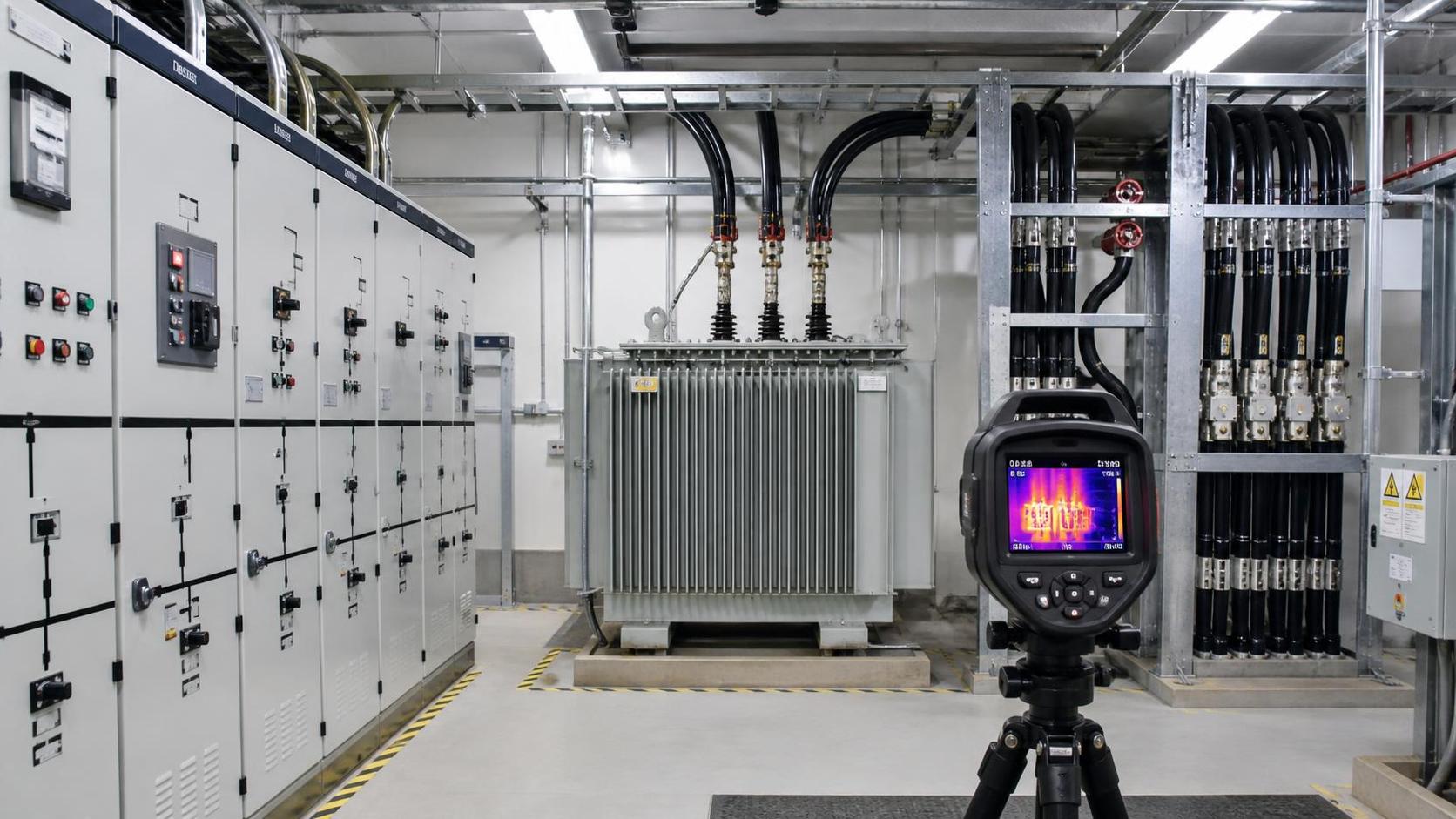
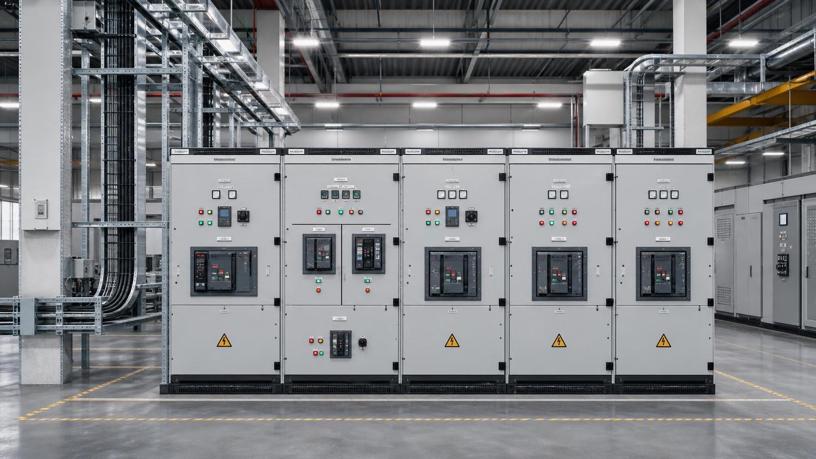
The image above reflects the system-level nature of modern facility power planning.
Industrial electrical infrastructure design is the coordinated planning of incoming power, transformation, distribution, control interfaces, grounding, protection, and emergency resilience within an operating site.
In practice, the scope starts at the utility connection or on-site generation point. It continues through substations, switchgear, motor control centers, busways, cable systems, control panels, and critical backup arrangements.
It also includes less visible choices that often decide long-term performance. Examples include fault level coordination, cable derating, environmental enclosure selection, arc flash mitigation, and spare capacity philosophy.
This broader definition matters because many project issues emerge in the interfaces. A well-rated transformer alone does not prevent trouble if protection settings, feeder segregation, or load assumptions are weak.
Why the topic matters more now
Industrial facilities are changing faster than their legacy electrical systems were designed to handle. Electrification, automation, digital monitoring, and tighter energy accountability are increasing system complexity.
At the same time, downtime has become more expensive. Production losses, safety incidents, damaged equipment, and compliance failures now travel quickly across supply chains and contractual obligations.
More projects are also cross-border. That raises the bar for harmonizing CE, UL, ISO, IEC, NFPA, and local utility requirements. Industrial electrical infrastructure design can no longer rely on a single domestic assumption set.
From a sourcing perspective, the challenge is equally practical. Lead times for switchgear, breakers, transformers, and metering hardware can reshape schedules, so early design quality reduces both technical and procurement friction.
Core components that define system resilience
Not every facility uses the same architecture, but resilient industrial electrical infrastructure design usually depends on a consistent set of building blocks.
Incoming power and transformation
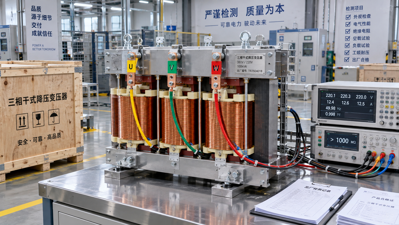
The source may be utility-fed, generator-backed, renewable-supported, or hybrid. Transformer sizing, redundancy level, and fault contribution analysis set the baseline for the rest of the network.
Primary and secondary distribution
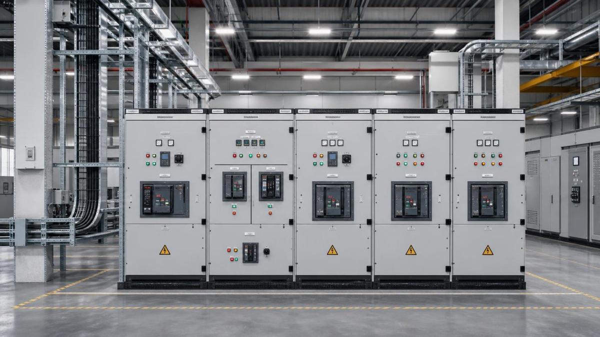
Switchgear, switchboards, panelboards, bus ducts, and feeders distribute power to process areas. Layout decisions affect voltage drop, maintainability, fire separation, and the ease of future plant expansion.
Motor and process power control
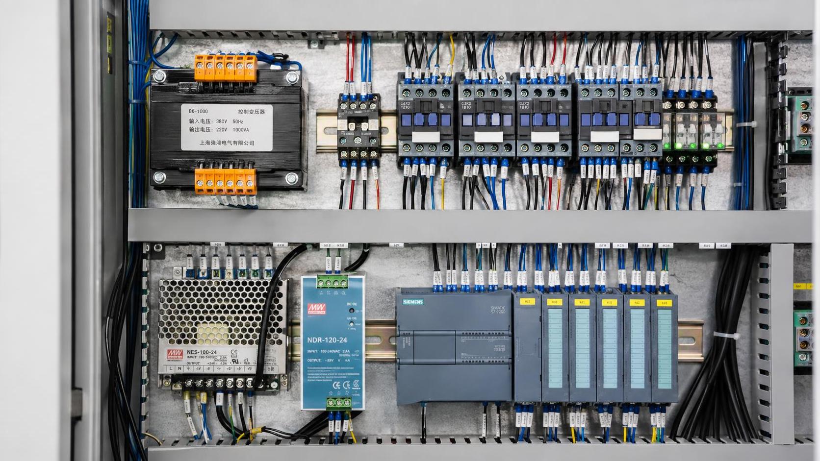
Motor control centers, variable frequency drives, soft starters, and process control panels introduce harmonic, thermal, and protection considerations. These loads often dominate operating behavior in industrial settings.
Protection, metering, and grounding
Protective relays, breakers, meters, surge protection, and grounding systems determine how safely the network responds under abnormal conditions. These elements are central to both compliance and asset protection.
Load planning is where strong projects separate from costly ones
Load planning is not a spreadsheet exercise added near the end. It is one of the most consequential parts of industrial electrical infrastructure design because it drives equipment ratings, network topology, and lifecycle economics.
The first distinction is between connected load and demand load. Connected load shows everything that could draw power. Demand load reflects how equipment actually operates by duty cycle, sequence, and diversity.
That distinction protects projects from two common mistakes. One is overdesign that inflates capital cost. The other is underdesign that creates nuisance trips, thermal stress, or expansion bottlenecks.
What accurate load studies should capture
- Normal operating demand by process area and shift pattern
- Motor starting current and voltage dip impact
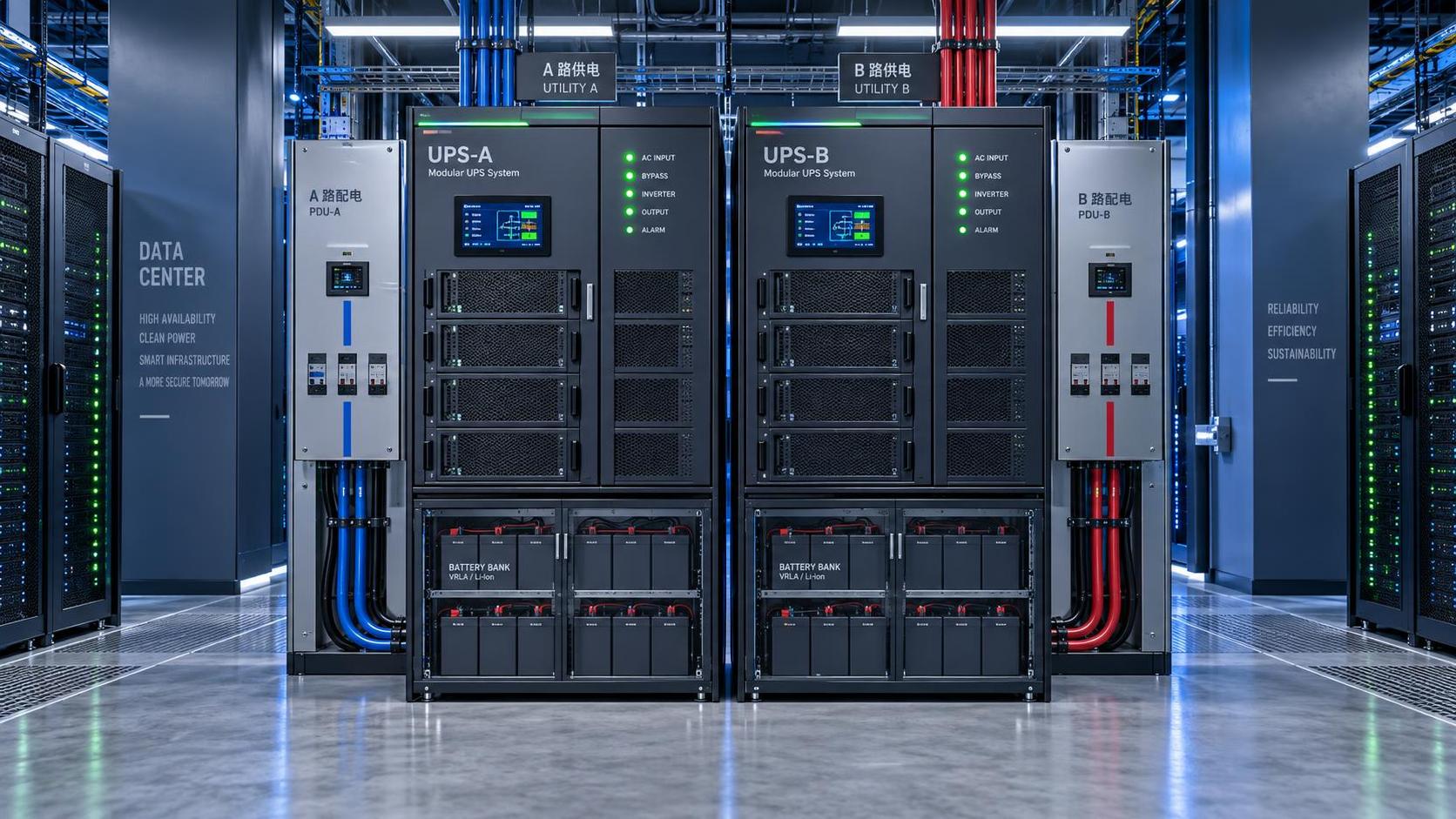
- Nonlinear load behavior from drives, UPS units, and electronics
- Future expansion allowance based on realistic project phases
- Critical load classification for backup or priority restoration
Usually, the best results come when electrical data is aligned with process design, instrumentation lists, mechanical schedules, and commissioning strategy. Isolated estimates often miss how the plant actually runs.
It is also worth checking load quality, not only quantity. Harmonics, poor power factor, transient sensitivity, and unbalanced phases can compromise system performance even when nameplate capacity appears adequate.
Safety codes are design inputs, not final paperwork
Compliance becomes expensive when treated as a handover-stage task. In effective industrial electrical infrastructure design, safety codes influence architecture, component selection, documentation, and testing from the beginning.
The exact framework varies by geography and industry segment. Still, most industrial projects must interpret a mix of IEC standards, NFPA practices, local electrical codes, CE or UL requirements, and ISO management expectations.
A few code-related issues deserve early attention because they regularly affect scope, budget, and site acceptance.
- Arc flash study requirements and labeling obligations
- Ingress protection and enclosure ratings for harsh environments
- Hazardous area classification and certified equipment selection
- Lockout isolation points and maintainable switching arrangements
- Documentation traceability for inspections, testing, and approvals
This is where data-driven editorial platforms such as GIC become useful reference points. Verified insight across safety, metrology, power systems, and environmental conditions helps reduce assumptions before procurement and installation begin.
Where design choices show up in day-to-day operations
The value of industrial electrical infrastructure design becomes visible after startup. Plants with disciplined planning usually commission faster and face fewer surprises during ramp-up and maintenance cycles.
In continuous process facilities, selective protection and redundant paths reduce the chance that a local fault becomes a site-wide outage. In batch operations, better load planning protects product quality during peak demand transitions.
Warehousing, utilities, metallurgy, water treatment, and manufacturing also place different demands on the electrical backbone. Some prioritize uptime, others motor-heavy loads, hazardous atmospheres, thermal extremes, or metering transparency.
That is why copying an old template rarely works well. A suitable design responds to the actual process profile, environmental stress, compliance exposure, and expansion roadmap of the site.
Practical checks before design freeze
Before a project locks major packages, a short set of review questions can reveal whether industrial electrical infrastructure design is robust or still too assumption-heavy.
- Is future capacity based on likely production phases rather than a generic margin?
- Have fault studies and protection coordination been updated with current vendor data?
- Do cable routes and equipment rooms support safe maintenance access?
- Are code, certification, and documentation requirements aligned across regions?
- Have procurement lead times influenced architecture and contingency planning?
These checks do not replace detailed engineering. They help confirm that the design can survive real project pressures, including revisions, substitutions, schedule compression, and later expansion demands.
A disciplined next step
The most useful next move is to review the electrical system as an operational platform, not a package list. Map critical loads, confirm realistic demand assumptions, and test every major decision against safety code exposure.
Where uncertainty remains, compare design intent with commissioning needs, maintenance access, and regional compliance pathways. That approach makes industrial electrical infrastructure design easier to evaluate before cost and schedule risks harden.
For organizations building global industrial assets, the strongest outcomes usually come from combining technical design review, verified standards intelligence, and disciplined sourcing judgment into one decision process.
Technical Specifications
- Air Handling Unit Supplier Checklist: Performance Data, Lead Times, and SupportAuthor :Environmental Engineering Director
- Buying Fiberglass Water Tanks Wholesale: Compare Quotes and Delivery CostsAuthor :Environmental Engineering Director
- Choosing an XLPE Power Cable Supplier: Test Reports, Traceability, and Lead TimesAuthor :Grid Infrastructure Analyst
Expert Insights

Chief Security Architect
Dr. Thorne specializes in the intersection of structural engineering and digital resilience. He has advised three G7 governments on industrial infrastructure security.
Related Analysis
- Oct 19, 2026Air Handling Unit Supplier Checklist: Performance Data, Lead Times, and SupportAuthor :Environmental Engineering Director
- Oct 18, 2026Buying Fiberglass Water Tanks Wholesale: Compare Quotes and Delivery CostsAuthor :Environmental Engineering Director
- Oct 17, 2026Choosing an XLPE Power Cable Supplier: Test Reports, Traceability, and Lead TimesAuthor :Grid Infrastructure Analyst
Core Sector // 01
Security & Safety
- Choosing a Step-Down Transformer Supplier: Test Reports, Lead Times, and WarrantyAuthor :Grid Infrastructure Analyst

- Metallurgy Processes That Improve Conductivity and Reliability in Power Grid ComponentsAuthor :Grid Infrastructure Analyst

- How to Size a UPS for Server Rooms: Load, Runtime, and Redundancy FactorsAuthor :Grid Infrastructure Analyst

- How to Choose a Step-Down Transformer for a Control Panel: Key Sizing FactorsAuthor :Grid Infrastructure Analyst

- How Often Should Overseas Power Systems Undergo Safety Inspections?Author :Grid Infrastructure Analyst

- How to Choose Panels for Extreme-Cold Industrial Sites?Author :Grid Infrastructure Analyst

- What Should a Cross-Border EPC Equipment Procurement Reference Include?Author :Grid Infrastructure Analyst

- How to Compare Low-Voltage Equipment for Panel IntegrationAuthor :Grid Infrastructure Analyst