How to Select XLPO Insulated Solar Cable for UV, Heat, and High-Voltage PV Systems
Author
Date Published
Reading Time
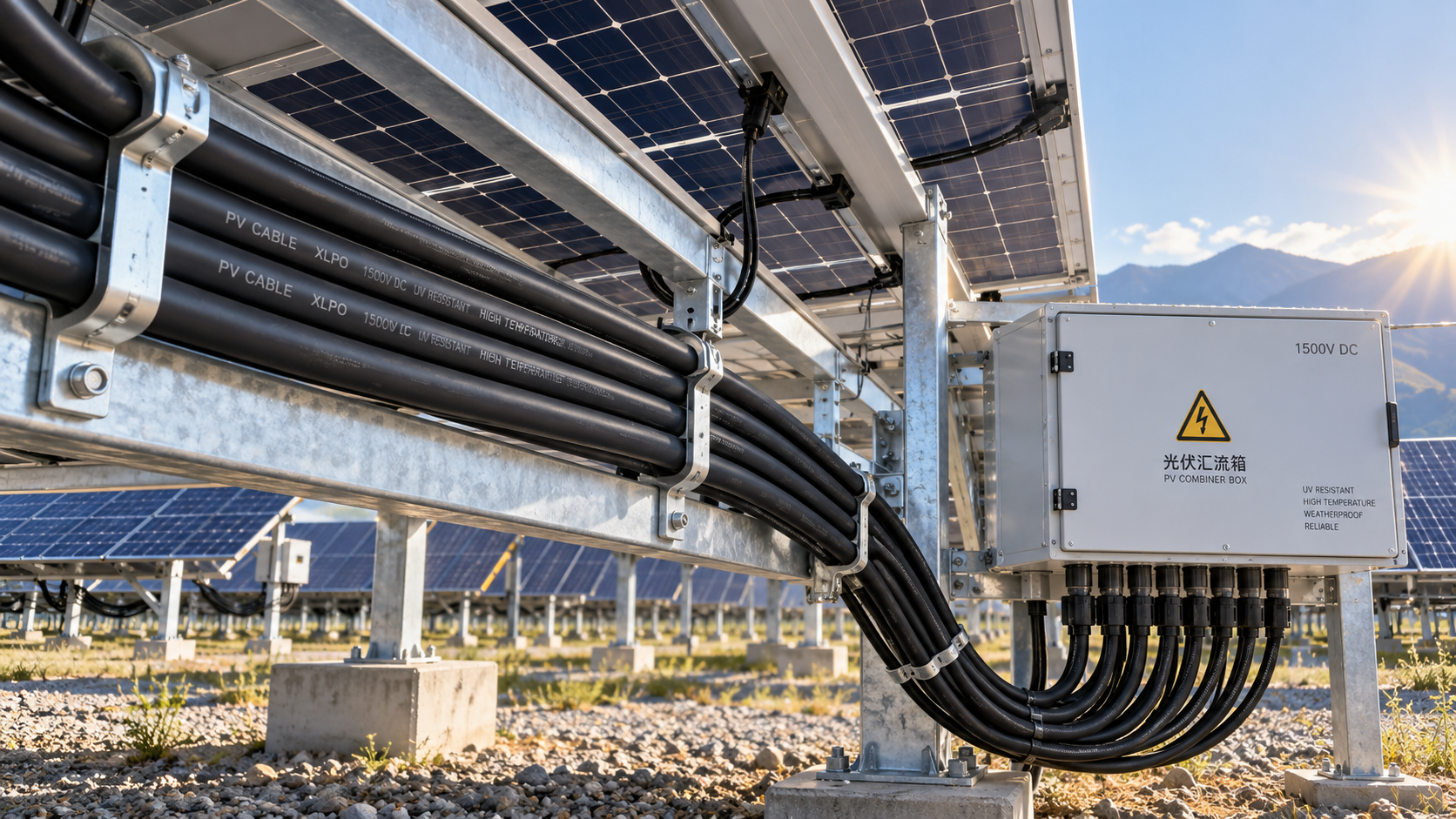
An XLPO insulated solar cable should be selected from the PV system's electrical design and installation environment, not from insulation material alone. XLPO can provide strong resistance to heat, ultraviolet exposure, ozone, and weathering, but a cable is only suitable when its voltage rating, conductor size, temperature capability, construction, and documented compliance all match the circuit it will serve.
For a rooftop array in a mild climate, the main concern may be long-term UV exposure and mechanical routing. For a utility-scale installation, high system voltage, thermal loading, cable grouping, and demanding pulling conditions may matter more. The same cable description can therefore be acceptable in one project and inadequate in another.
The practical starting point is simple: define the circuit, voltage architecture, installation path, and environmental stress before comparing catalogues. A cable should then be evaluated as part of the complete DC wiring system, including connectors, junction boxes, cable management, terminations, and protective devices.
Start with the circuit, not the insulation label
“XLPO” generally refers to cross-linked polyolefin insulation or sheathing. Cross-linking improves the material's ability to retain useful properties under sustained heat and outdoor exposure compared with many general-purpose thermoplastic cable compounds. That makes it common in photovoltaic cable designs. It does not, however, establish the cable's current capacity, voltage suitability, flexibility, or installation approval.
Before specifying an XLPO insulated solar cable, identify whether it will be used for module leads, string homeruns, combiner-to-inverter wiring, battery-side DC circuits, or another part of the installation. These applications may have very different electrical and mechanical demands.
- Module and string wiring usually needs high flexibility, durable insulation, reliable connector compatibility, and resistance to repeated thermal cycling.
- Long DC runs require conductor sizing based on both safe ampacity and voltage drop. A cable that safely carries current can still create avoidable energy loss if its cross-section is too small for the route length.
- High-voltage PV strings need a voltage rating that covers the system's highest possible DC voltage, including cold-weather open-circuit conditions and the design margin required by the project.
- Equipment interconnections may face tighter bending spaces, conduit-fill limitations, vibration, or additional requirements imposed by the equipment manufacturer and the installation method.
A common procurement mistake is to begin with a familiar conductor size and then search for an outdoor-rated cable in that size. The safer sequence is to calculate the circuit duty first, establish the required voltage class, and then shortlist cable constructions that are approved for the intended environment.
High voltage: assess the complete DC stress
PV systems operate differently from ordinary low-voltage AC branch circuits. A string's DC voltage is influenced by module count, module electrical characteristics, and temperature. Cooler conditions can raise open-circuit voltage, so the nominal operating value is not the sole design input. The cable, connector, fuse holder, isolator, combiner components, and inverter input must all be appropriate for the same DC voltage architecture.
Do not treat a cable's voltage marking as a generic measure of quality. It is a defined limit associated with a particular construction and applicable test or approval basis. Selecting a higher-rated cable may be sensible where the system design requires it, but it does not compensate for undersized conductors, poor termination practices, or mismatched connectors.
Technical reviews should also distinguish between a cable intended for PV DC circuits and a general outdoor cable that happens to have a similar nominal voltage rating. PV cable designs are commonly built around the combined conditions of outdoor sunlight, elevated surface temperatures, DC operation, and long service life. Similar-looking cable can differ substantially in insulation formulation, sheath robustness, conductor stranding, and test documentation.
UV and heat resistance need to match the installation path
UV resistance matters most where the cable is exposed to direct sunlight for long periods: on open racks, roof surfaces, tracker structures, and transitions between equipment. In those areas, the outer sheath is the first line of defense. It must resist cracking, embrittlement, fading that obscures identification, and loss of mechanical integrity over time.
Heat exposure is more complicated than ambient air temperature. Cable temperature can rise because of solar gain on dark surfaces, restricted airflow beneath modules, proximity to hot roofing materials, high current, bundled circuits, or installation inside enclosures. A conductor's electrical losses also create heat, which is why conductor selection and cable routing cannot be separated.
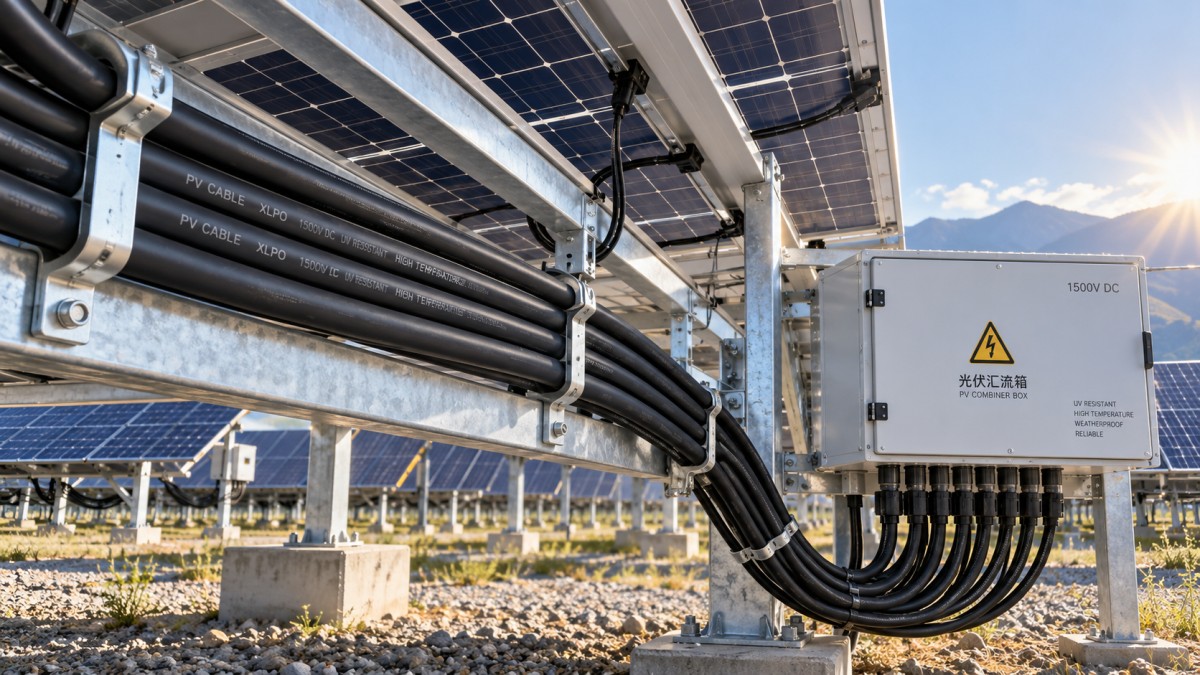
When comparing options, request evidence that the proposed cable construction is intended for the actual exposure. The useful questions are not “Is it UV resistant?” or “Is it heat resistant?” in isolation. Ask whether it is suitable for direct outdoor exposure, the expected temperature range, the specified routing method, and the relevant PV application. A cable routed in shaded conduit may face a different balance of risks from a cable clipped directly to a sunlit metal support.
XLPO is often a sound choice for exposed solar wiring because cross-linked material can tolerate demanding thermal and environmental conditions. It is not a universal answer. If the route passes through a location with chemical exposure, standing water, persistent abrasion, rodent risk, or unusual mechanical movement, those hazards require their own evaluation. A UV-resistant sheath does not automatically provide the needed resistance to every site-specific threat.
Conductor size is a system-performance decision
Conductor cross-section affects more than whether the cable remains within its thermal limit. In DC PV circuits, resistance over distance produces voltage drop, which can reduce usable energy and complicate performance expectations. Long runs from remote arrays or combiner locations deserve particular attention.
Current-carrying capacity must be assessed in the installed condition. Published values can change with ambient temperature, conductor grouping, conduit use, ventilation, number of loaded circuits, and local installation rules. A freely ventilated single cable and a tightly packed bundle beneath modules do not dissipate heat in the same way.
Copper conductors are frequently preferred where compact routing, flexibility, and dependable termination behavior are priorities. Fine-stranded construction can make installation easier around module frames and crowded equipment, but it must be terminated with lugs, ferrules, and connector systems designed for that conductor type. The cable specification and termination method should be reviewed together; a correct cable can still fail at an incorrectly selected or poorly crimped termination.
Read the construction details that catalog summaries omit
Two solar cables with the same conductor size and broad XLPO description may perform differently in the field. The data sheet should be read beyond the headline rating.
Insulation and sheath arrangement
Some cables use distinct insulation and outer-sheath layers, while others use constructions optimized for smaller PV interconnections. A robust outer layer is valuable where cables contact mounting hardware, pass through clips, or are exposed to handling during installation and maintenance. Examine whether the construction suits the expected abrasion and handling, rather than assuming a thicker-looking cable is always preferable.
Flexibility and bending control
Flexible cable reduces installation strain around modules, junction boxes, and cable-management hardware. Excessive bending remains a problem even with flexible conductors. It can damage insulation, deform the conductor bundle, or load connector terminations. Verify the manufacturer's bend-radius guidance and make sure the physical route allows it, especially at equipment entries and under array edges.
Marking and traceability
Clear, durable cable marking supports installation inspection, maintenance, and replacement years later. The marking should identify the manufacturer, conductor size, voltage designation, and applicable approvals or standards claimed for the product. Unmarked or poorly marked cable creates unnecessary uncertainty during acceptance checks and fault investigation.
Compliance evidence should be specific to the cable offered
Project specifications often refer to regional electrical rules, purchaser requirements, or recognized certification schemes. These requirements vary by jurisdiction and installation type, so the engineering team should define the applicable framework before purchase. The important point is that paperwork must describe the exact cable construction being supplied, not a related product family or a marketing claim.
Ask the supplier for the current technical data sheet, declaration or certificate documentation where relevant, and a clear product code linking those documents to the proposed cable. Review whether the document addresses PV use, outdoor exposure, voltage class, temperature capability, conductor construction, and flame or smoke requirements when those are relevant to the route. For large or safety-critical procurement packages, this document review should occur before bulk delivery, not after cable is installed.
It is also prudent to verify the cable against connector instructions. Connector manufacturers can limit compatible conductor sizes, strand constructions, insulation diameters, and stripping lengths. Mixing connector brands or using a cable outside the connector's approved range can create elevated contact resistance, poor sealing, or unreliable retention even when each item appears suitable on its own.
Where XLPO solar cable is not enough by itself
An XLPO insulated solar cable is appropriate for many exposed PV DC applications, but it should not be treated as a substitute for mechanical protection. Cable suspended loosely across sharp structure edges, resting on abrasive roofing, exposed to traffic, or routed where water can accumulate needs a better installation design. Clips, guards, conduit, trays, edge protection, and appropriate support spacing are often as important as insulation chemistry.
Special environments also need an additional screening step. Coastal sites may require attention to corrosion of clips and terminations. Agricultural or industrial areas may expose cable to chemicals. Ground-mounted arrays can face rodent damage and vegetation maintenance. Floating or water-adjacent installations introduce humidity and movement concerns. In each case, decide whether the base PV cable construction needs supplementary protection or a different cable system for a particular section of the route.
A practical review sequence before release
- Map each DC circuit and identify its maximum voltage, design current, route length, and termination points.
- Define the physical environment for every cable section, including sunlight, roof heat, grouping, conduit, abrasion, moisture, and movement.
- Size the conductor for installed ampacity and acceptable voltage drop, applying the project’s required derating approach.
- Select a PV-suitable cable construction with XLPO insulation or sheathing where its environmental and thermal properties address the actual exposure.
- Confirm compatibility with connectors, lugs, glands, conduit fittings, clips, and protective devices.
- Review product-specific documentation and preserve the approved cable data in the project record.
- Inspect delivered drums or coils for correct marking, damage, and traceability before installation begins.
The best specification is usually not the cable with the most impressive standalone description. It is the cable whose voltage rating, conductor size, XLPO construction, documented suitability, and installation method all align with the defined PV duty. That approach prevents a frequent failure in solar procurement: selecting cable for outdoor appearance and price, then discovering too late that the electrical design, connector system, or site conditions demand something more specific.
Technical Specifications
- Air Handling Unit Supplier Checklist: Performance Data, Lead Times, and SupportAuthor :Environmental Engineering Director
- Buying Fiberglass Water Tanks Wholesale: Compare Quotes and Delivery CostsAuthor :Environmental Engineering Director
- Choosing an XLPE Power Cable Supplier: Test Reports, Traceability, and Lead TimesAuthor :Grid Infrastructure Analyst
Expert Insights

Chief Security Architect
Dr. Thorne specializes in the intersection of structural engineering and digital resilience. He has advised three G7 governments on industrial infrastructure security.
Related Analysis
- Oct 19, 2026Air Handling Unit Supplier Checklist: Performance Data, Lead Times, and SupportAuthor :Environmental Engineering Director
- Oct 18, 2026Buying Fiberglass Water Tanks Wholesale: Compare Quotes and Delivery CostsAuthor :Environmental Engineering Director
- Oct 17, 2026Choosing an XLPE Power Cable Supplier: Test Reports, Traceability, and Lead TimesAuthor :Grid Infrastructure Analyst
Core Sector // 01
Security & Safety
- Choosing an XLPE Power Cable Supplier: Test Reports, Traceability, and Lead TimesAuthor :Grid Infrastructure Analyst

- How to Select XLPO Insulated Solar Cable for UV, Heat, and High-Voltage PV SystemsAuthor :Grid Infrastructure Analyst

- Selecting PTFE Insulated Hookup Wire for High-Temperature Control PanelsAuthor :Grid Infrastructure Analyst

- How Contractors Can Evaluate EPC Sourcing Solutions for Cost, Lead Time, and RiskAuthor :Grid Infrastructure Analyst

- What Drives Silicone Cable Bulk Price in Industrial Orders?Author :Grid Infrastructure Analyst

- EN 61000-6-4:2026 Takes Effect for EU-Bound ControlsAuthor :Grid Infrastructure Analyst

- How to Choose Low Smoke Cables and Wiring for Safer Commercial Buildings?Author :Grid Infrastructure Analyst

- Medium Voltage Armored Cable Selection Guide: Voltage Rating, Armor Type, and InstallationAuthor :Grid Infrastructure Analyst